Computerized Labyrinth Solver
Part. Quantity. Cost. Logitech Quickcam. 1. $30.00. Motorolla 68HC12 Board (Provided by RIT). 1. ~$100.00. Servo Motors. 2. $15.00. Notches for the wall segments. …. PC for Video Tracking (Provided by User). 1. N/A. Wall Segment. …. . . . . . . . . .

Computerized Labyrinth Solver
E N D
Presentation Transcript
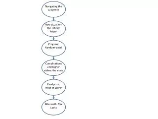
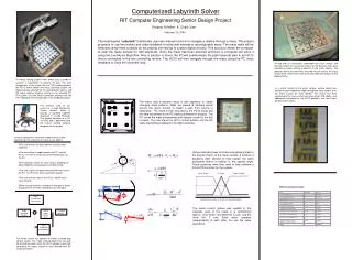
Part Quantity Cost Logitech Quickcam 1 $30.00 Motorolla 68HC12 Board (Provided by RIT) 1 ~$100.00 Servo Motors 2 $15.00 Notches for the wall segments … PC for Video Tracking (Provided by User) 1 N/A Wall Segment … . . . . . . . . . Lumber for construction N/A $25.00 … Copperplated Circuit Board 1 $5.00 Notches for Start and End tabs Etching Solution and materials N/A $20.00 Input Disturbances from surface 74LS151 8:1 Line Multiplexer 16 $10.00 74LS153 2:1 Line Multiplexer 2 $2.00 Target Reference Position Servo motor control plant Final Ball position Various Connection pieces (Headers, Jumpers, Cables) N/A $30.00 + Total: $237.00 Video recognition and feedback Computerized Labyrinth Solver RIT Computer Engineering Senior Design Project Gregory Schallert & Chad Craw February 12, 2004 The board-game ‘Labyrinth’ traditionally uses two manual controls to navigate a marble through a maze. This project proposes to use two motors and video feedback to solve and traverse a reconfigurable maze. The maze walls will be detected using metal contacts on the playing connecting to custom digital circuitry. This structure allows the computer to scan the maze surface for wall segments. Once the maze has been scanned and built, a Computer will solve it using the Lee Moore Algorithm. After a solution is found, the PC will communicate the path traversal plan to an HC12 that is connected to the two controlling motors. The HC12 will then navigate through the maze using the PC video feedback to close the controller loop. To help with size constraints underneath the maze surface, and alleviate weight, the connection points for the dynamic walls were created by custom etching a board to fit the maze (above). The opposite side of this board was cleaned off and used as the maze surface itself, while these trace routes provided connections for the digital circuitry. The Maze solving system shown above uses a number of systems in conjunction to perform it’s task. The main components of the system are the CCD tracking camera, the HC12 motor control and maze scanning system, the digital circuitry attached to the wall detection points, and the video tracking software running on an attached PC. The system uses the Serial Connection Interface with the HC12 board to communicate data in the feedback process. In a similar fashion to the maze surface, another board was etched to accommodate the digital multiplexer array used to scan the maze surface for walls (below). This circuit was then connected to the maze surface using two 40-pin IDE cables, and additionally connected to the HC12 controller with two 16-pin parallel socket cables. The maze uses a dynamic array of wall segments to create changing maze patterns. Walls are placed at arbitrary points around the maze surface to create a path from source to destination. The maze is then scanned by the HC12 board and the data transmitted to the PC tracking software for analysis. The PC solves the maze preemptively and designs a path for the ball to travel. The user starts the HC12 control system, and the PC starts transmitting feedback to the Microcontroller. The Camera used for our system is a Lego Mindstorms Visions camera, which is actually a standard Logitech Quickcam in a Lego Package. The camera connects to a PC via USB, and is operated using the custom tracking software designed for this project. • Once all connections have been made and the system powered up, the sequence of events are as follows: • The user defines the walls location using the wall segments. • The connection is made between the PC and the HC12. The HC12 sends the current wall locations to the PC. • The Computer solves the maze using a modified Lee Moore Algorithm and waypoints are determined. • The user selects the object they would like to track on the PC. The PC then starts tracking the object. • The user presses start on the HC12 and the maze starts moving. • When the ball reaches a waypoint a new goal is found. Displacements are then calculated to the new goal. Using some basic laws of motion and applying them to the angular motion of the maze surface, a number of equations were derived to help explain the ball’s anticipated motion in relation to the applied angle. These equations were then used to help calibrate a Fuzzy PID controller for the system. Left of Target At Target Right of Target Materials for Construction: Membership Function for the Error in the ball’s position The same control system was applied to the separate axes of the maze in a symmetrical fashion. One motor controlled the X axis, and the other the Y axis. Each motor operates independently of each other, but use the same algorithms. The whole system ties together to create a closed loop control system. The Video tracking determines the path for the ball to travel, while the HC12 concerns itself with controlling the motors based on input derived from the tracking software.