Download
1 / 21
220 likes | 426 Vues
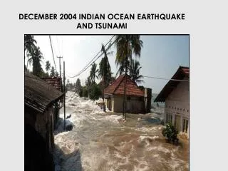
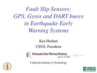
Fault Slip Sensors: GPS, Gyros and DART buoys in Earthquake Early Warning Systems. Ken Hudnut USGS, Pasadena California Institute of Technology. Session title - Looking at the Future… High risk approach specific to rare event with great consequences Bayes’ Theorem applied to system design?.

E N D
Fault Slip Sensors:GPS, Gyros and DART buoysin Earthquake EarlyWarning Systems Ken Hudnut USGS, Pasadena California Institute of Technology
Session title - Looking at the Future…High risk approachspecific to rare eventwith great consequencesBayes’ Theorem applied to system design? Instrument Simmler and Coachella Valley segments of San Andreas fault and Subduction zones at trench and wedge tip
Define “priors” Expected “Big One” source rupture is expected on the San Andreas fault or mega-thrust at trench If fault slip occurs at surface, it must be the case that a “Big One” is in progress (system depends on it)
Sensor technology GPS & DART Gyro Accelerometer position displacement velocity acceleration Frequency response
Gyros Proper transducers for the EEW job:borehole strain, tilt, strong motion, GPS, gyros? GPS Gyros Langbein & Bock (2003) Courtesy of John Langbein (USGS)
GPS/INS (RLG) inairborne imaging: • GPS aircraft trajectory relative to ground-based GPS array • INS (gyro) for aircraft attitude • Laser mirror and/or camera position and orientation very well known • New imaging capabilities (also for satellite imagery)
Sagnac Interferometer Designed to sleep for decades then wake up quickly and perform flawlessly for several minutes RLG’s & FOG’s
Gyros and MEMS with GPS • Stable gyro technology is costly but MEMS-gyro and FOG are lower cost and approaching accuracy Barbour & Schmidt, 1998
Lone Juniper Ranch and Frazier Park High School First prototype GPS fault slip sensor; up to 10 Hz (Hudnut et al., 2002) Spans the San Andreas fault near Gorman, California
GPS high-rate (1 Hz) analysis • Larson, Billich and Choi - see Ji et al. • Sidereal filtering (Larson, Choi) • Stacking (Billich) • Significant reduction in long-period drift • Compares well now with our static GPS displacements
Doubly-integrated seismic vs. GPS for Parkfield 2004 (co-located @ PHOB) Raw GPS solution in blue Filtered GPS in green Seismic in red (Boore) These show results prior to final GPS analysis step of stacking, shown previously
Simplifying assumptions… Sensor technology exists: Inertial BB seismic, accelerometers, gyros GPS - will keep improving Telemetry technology exists Price is no concern ;-) “blue sky”
San Andreas fault • 35 mm/yr slip rate; • >70% of plate motion • 1685, 1857 eq’s • SoCal is now well ‘wired’ • Likely source of most future ‘Big Ones’ • Fault physics experiment • GPS/INS in near-field • ALSM & DG scan ‘net’ • Great place to test EEW • Build “zipper” arrays • Cholame - Simmler • Coachella Valley
San Andreas - place two betsboth ~120 km from Los Angeles (LA) Coachella Valley segment is ~60 km to San Bernardino L A
Measure fault slip at the source! Geist & Dmowska (1999) On-land GPS are great to have, but unfortunately do not resolve the shallow slip at the trench, which is vital for distinguishing a “tsunami earthquake”
Initial test off Japan (not real-time) - could be done also for Cascadia & Alaska Large bedforms NOAA DART buoys could be applied to real-time slip detection application - a seafloor implementation of the Fault Slip Sensor concept Geist (1999) has suggested that Kanamori’s “tsunami earthquakes” are due to large rapid slip at the sea floor
NOAA - Frank Gonzalez &Vasily Titov’s ‘dream’ for teletsunami sources and local tsunami sources real-time pattern of seafloor displacements (esp. vertical since slopes are slight) system works for undersea landslides or earthquake sources sensors - IMU’s (accel. & gyro) telemetry - seafloor cables for Cascadia, work with NEPTUNE and on-land w/ ANSS and PBO - upgrades needed
Summary • Slip sensor concept is to augment regional seismic coverage - one part of an overall EEW system that is primarily using a very different approach • Measure slip directly - don’t need to know anything else - ‘quick & easy’ • High risk deployment strategy tuned to rare pay-off in extreme events • Robust earthquake early warning system design • obtain more accurate displacement observations (e.g., Pd) • new instrumentation for dynamic and static displacement address deficiencies due to double-integration of accelerometer records • RLGs, FOGs, MEMs-gyros and GPS all complement accelerometers (which alone are deficient in measuring displacement, tilt and rotation) - these sensors are dropping rapidly in cost - should be further evaluated for use in earthquake early warning
Finally - another technological advancefor EEW message delivery? Cell phone with GPS (location!) opens possibility of SMS real-time warning to mobile users (outdoors) or mobile platforms (e.g., cars) - currently not feasible due to power requirements (if GPS on all the time) Maps2ME FutureRoads