Physics and Detectors at Linear Colliders
680 likes | 905 Vues
Physics and Detectors at Linear Colliders. Jan Strube CERN on behalf of the SiD detector concept. Outline. Physics Motivation The ILC Accelerator Requirements for Detectors SiD - a Detector for the ILC Simulation Studies Summary / Outlook. The Higgs. The Discovery of a Higgs Boson.

Physics and Detectors at Linear Colliders
E N D
Presentation Transcript
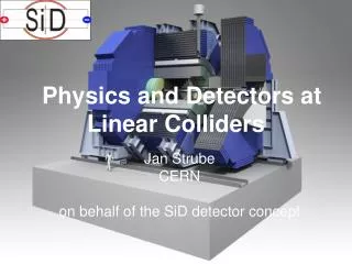
Physics and Detectors at Linear Colliders Jan Strube CERN on behalf of the SiD detector concept
Outline • Physics Motivation • The ILC Accelerator • Requirements for Detectors • SiD - a Detector for the ILC • Simulation Studies • Summary / Outlook
Measurements of Higgs Couplings Now... Focus changes from searches of Higgs bosons to measurements of Higgs properties: Spin Coupling to other Standard Model particles
Premise: “To me, it’s the ILC”
Measurements of Higgs Couplings … in the future M. Peskin Extrapolation from Snowmass submissions. ILC has clear advantage in measurement of Higgs branching ratios to b, c and invisible. Total width directly accessible, measurements are absolute
How well do we need to measure the Higgs boson couplings? A: It depends… see [Gupta, Rzehak, Wells, arXiv:1206.3560] for details
ILC Physics Case • Precision measurements of Higgs Boson properties and interactions with the rest of the Standard Model will be one of the cornerstones of particle physics for the foreseeable future • The ILC offers significant and important advantages over existing facilities for Higgs physics • Physics potential is maximized in staged construction, (91 GeV/)250 GeV - 1 TeV: SM precision, top, Higgs, SUSY
The ILC accelerator Superconducting technology: 8000 cavities, cooled to 2K Built in stages First stage: 250 GeV Baseline: 500 GeV Luminosity: 1.8 x 1034 cm-2s-1 Repetition rate: 5 Hz Damping Rings Technology proven to work: FLASH (DESY) XFEL (DESY) Undulator for positron production
Japanese Candidate Site Chosen Announcement on 23rd Aug. 2013: Kitakami site chosen for Japan’s bid to host the ILC Sites were scored on technical and sociological aspects
ILC Beam Structure 1312 bunches, separated by 554 ns • Beam structure allows high granularity design. • Accumulate data during bunch train • Read out in quiet time. • No trigger needed: Expect one hadronic Z decay per train • Background and radiation low compared to LHC. Allows to build low-mass tracking systems.
The ILC Physics Program First Stage: 250 GeV • Higgs recoil mass • Higgs BR Second Stage: 500 GeV (baseline) • Higgs BR • Higgs width • top physics (threshold scan) • Higgs self-coupling Third Stage: 1000 GeV • Top Yukawa coupling • Maximum discovery potential for new physics
Top threshold scan Unique feature of lepton colliders: Threshold scan Top mass at LHC: Pythia templates Translation to theoretically well-defined quantity difficult Top mass measured in threshold scan at ILC translates directly to well-defined MS mass. Δmtop< 100 MeV, dominated by theory uncertainty
Higgs Physics at the ILC Higgs width Higgs BR: second generation fermions c quarks, muons Higgs Recoil method: First sensitivity to invisible decays Higgs self-coupling: Top Yukawa coupling
Recoil Mass measurement Reconstruct the Z boson Known √s Invariant mass of the recoiling event Unique capability of lepton colliders: Well-known initial state Reconstruct the Z boson, the invariant mass of the recoiling event peaks at the Higgs mass ZH → μ+μ- + anything, 250 GeV, 250 fb-1
Physics Requirements ZH → μ+μ- + anything 250 GeV Momentum resolution Higgs Recoil σ(pT)/pT2 ~ 2-5 x 10⁻⁵ GeV-1 Jet Energy Resolution Separation of W/Z/H bosons: Gauginos, Triple Gauge Coupling σ(E)/E = 3.5%-5% Flavor Tagging Higgs Branching ratios σrφ ≈ 5 μm ⊕ 10 μm / (p[GeV] sin3/2θ) W-Z separation primary vertices in tth events ILC 1 TeV
Goals for Detector Design ILC environment allows to optimize for resolution Calorimeter Granularity: ~ 200x better than LHC Pixel Size: ~ 20x smaller than LHC Material budget, central region: ~ 10x less than LHC Material budget, forward region: ~ 100x less than LHC
Motivation for Particle Flow Reconstruction High resolution is key to precision measurements Goals: - equivalent luminosity - W / Z separation for gaugino analyses and anomalous triple gauge coupling measurement 10% Jet energy resolution 5% Jet energy resolution
Introduction to Particle Flow Reconstruction I Tracker: low material, high momentum resolution, high impact parameter resolution tracks ECAL: - High number of radiation length (typically 15-30 X0) - good energy resolution (typically σE/E ≈ 5-20%/√E) HCAL: - High number of interaction lengths (typically 5-8 λ0) - good energy resolution (typically σE/E ≈ 50-100%/√E)
Introduction to Particle Flow Reconstruction II Ideally, fully reconstruct the shower for each particle and match tracks to showers. At higher jet energies, confusion (mis-matching of energy depositions and particles) deteriorates the resolution. At even higher energies, leakages becomes a factor in the jet energy resolution. PFA possible without high granularity At CLIC: High granularity essential for background reduction
Introduction to Particle Flow Reconstruction III • Find muons, subtract hits from calorimeter • Find tracks • Match tracks to clusters in the ECAL • Iterative re-clustering to ensure consistency between track and cluster energy • Remove hits matched to a track • Photon finding in the ECAL • Rest is neutral Hadrons
Introducing SiD Co-spokesperson A. White UT Arlington Co-spokesperson M. Stanitzki DESY An international group studying a detector concept for LCs Home Institutions for Editors of the SiD Detailed Baseline Report
The SiD Detector Concept at the ILC Flux return, instrumented for muon identification Highly granular SiW ECAL 10 layer silicon tracking system 5 layers pixel 5 layers microstrips ~ 2.5 m Highly segmented HCAL, 60 layers 5 Tesla field
The SiD Detector Concept at the ILC A compact, cost-constrained detector designed to make precision measurements and be sensitive to a wide range of new phenomena Design Choices: - Compact Design in a 5 T field - Robust all-Silicon tracking with excellent momentum resolution - Time-stamping for single bunch crossings - Highly granular calorimetry optimized for Particle Flow - Integrated Design: All parts work in tandem - Iron flux return / muon identifier is part of SiD self-shielding
Milestones Validated Concept and its performance at various collision energies documented in several documents. SiD was validated by IDAG in 2009.
The DBD The DBD describes the baseline choices for all sub-detectors (except the vertex detector) Options have been kept This baseline is fully costed Options offer better performance and/or lower cost Not as mature as baseline choices The DBD is a waypoint on the road to the SiD TDR and beyond. R&D continues.
Outer Tracker Low material budget ↔ excellent momentum resolution In an all-silicon tracker, this means: • thin sensors • advanced integrated electronics • low-mass support • low power ↔ low-mass cooling Hermetic coverage
KPiX - System on a chip KPiX as a Calorimeter chip 1024 channels prototype under test - optimized for ILC (1 ms train, 5 Hz train repetition rate) • Low noise dual range charge amplifier with 17 bit dynamic range • Low noise floor 0.15 fC (1000 e−) • Designed for power modulation, average power < 20 μW / channel • Internal calibration system • Up to four measurements per channel per train • Versatile Baseline for Tracker and ECAL. KPiX as a Tracker chip First revision of pigtail cable has been tested. Second revision has been ordered.
Tracking Performance Excellent momentum resolution, impact parameter resolution and track finding efficiency even in high-energy jets
Vertex Tracker 5 Barrel layers Beam pipe Excellent impact parameter resolution for reconstruction of secondary and tertiary vertices Several technologies potentially meet the requirements: 3D, SOI, MAPS, hybrid pixels, DEPFET 5 pixel layers in barrel Innermost layer at 14 mm 4 disks ~ 20x20 μm2 pixels 3 forward disks ~ 50x50 μm2 pixels 3 Forward disks 4 disks R&D for extremely low-mass support structures: All-silicon assembly, foam-based ladders (PLUME collaboration), carbon fibre supports SiD is designed to make insertion and removal of the Vertex Detector straightforward. Allows to take advantage of the best possible technology.
Pixel Technology Examples Prototype 2 pixel layout Chronopix: Monolithic CMOS chip with time stamp memory for a whole bunch train. 25x25 μm2 pixels currently, 90 nm technology. Full prototype to have 10x10 μm2 or 15x15 μm2, will go to 45 nm technology. 3D technology: Top interconnect can be done in final topside aluminum patterning with low mass. Cables bump-bonded to end of ladders. Allows for all-silicon design.
Vertex Finding and Flavor Tagging performance Vertex detector to find decay point of long-lived particles (vertices): b and c quarks, τ leptons Flavor tagging is the identification of b, c or light quark jets.
Calorimetry Tree Subsystem Absorber Readout Si-Pads ECAL Tungsten MAPS GEM HCAL Steel Micromegas RPC SiPM Steel Muon System SiPM RPC Baseline Digital Readout Analog Readout Option
Si-W ECAL Highly segmented in lateral and transverse directions Hexagonal shapes Readout with KPiX chip 20 layers 2.5 mm W (5/7 X0), 10 layers 5 mm W (10/7 X0) 1.25 mm gaps → 29 X0, 1 λ ΔE / E ≈ 17% / √E Test in SLAC ESA beamline in July 2013, <15 of the full 30 layers; All layers for later running in 2013-14 The R&D provides the required baseline ECal components (except large-scale mechanics) – now nearly completed
Digital HCAL ~ 500,000 channels World record for hadronic calorimetry 54 glass RPC chambers, 1m2 each PAD size 1×1 cm2 Digital readout (1 threshold) 100 ns time-slicing Fully integrated electronics Main DHCAL stack (39) + tail catcher (15) CERN test setup includes fast readout RPC (T3B) W-DHCAL π- at 210 GeV (SPS)
HCAL HCAL in the Steel absorber stack at FNAL Highly granular calorimeter - 1x1 cm2 readout pads. World record for number of channels in hadron calorimetry already in test stack. Baseline: Glass RPC, digital readout Technology successfully tested in beam tests in steel absorber stack at FNAL and in tungsten absorber stack at CERN Data analysis is underway Operational experience drives further R&D: Single-glass RPC, low-resistivity glass for lower multiplicity, higher rate Energy resolution of pions all pions longitudinally contained
Forward Systems LumiCal: 40 mrad < θ < 90 mrad - to measure integrated luminosity to better than 10-3 - read out by Bean, KPiX BeamCal: 3 mrad < θ < 40 mrad - to measure instantaneous luminosity using pairs - read out by Bean chip Bean Chip developed for higher radiation dose, high occupancy in far forward region 180 nm CMOS
Solenoid Wes Craddock, SLAC, SiD Workshop, Jan. 2013 5 T coil with Detector Integrated Dipole (DID) Coil Design builds on CMS experience. Advances in computation give a significant advantage to the SiD design as compared to prior CMS design work - Magnetic field calculations in 3D ANSYS model - Conservative choice of material. Feasibility demonstrated. - Further conductor R&D could lead to cost savings.
Muon Instrumented Flux Return. Main purpose: - Identification of muons - Rejection of hadrons Barrel Endcap Barrel: Double layers of orthogonal strips, glued together with aluminum sheets Endcap: Strip size adjusted to fit between spacers Wavelength-shifting fibers read out by SiPM in a mounting block 10 layers in barrel, 9 in each endcap Major change since LOI: RPC → Extruded Scintillator bars, SiPM readout Technology successfully tested in FNAL beam.
Engineering and Push-Pull Horizontal access site SiD barrel fixed on 3.8 m concrete platform for push-pull Endcaps can be routinely opened for service Specific push-pull planning depends on IR layout "Fastest turnaround that is safely achievable": estimated 32 hrs
Data Rates “Back-of-the-envelope” calculations: • ILC 1 TeV: 1.06 GB / train data rate from detector,~ 5.3 GB / s RAW data • CLIC 3 TeV: ~ 200 GB / s RAW data from detector~ 10 GB/s sustained data rate to be written to disk (using today’s EDM and file format and estimating potential for data reduction) • LHC: Alice farm (2011) able to achieve ~ 5 GB / s sustained data rate to disk Farm size (CLIC 3 TeV): Estimated at 19k nodes of today’s nodes with today’s software. Size of CMS online farm (2011): 7.5k nodes
Costing Costing units agreed between SiD, ILD, CLIC: 2008 USD SiD uses central values of agreed costs Cost of baseline: • M&S: 315 MCU • Contingency: 127 MCU • Effort: 748 person-years Parametric detector costing → cost sensitivity analysis Baseline: 6 CU / cm2 Si Coil costed as being made by industry 3 CU / cm2 Si, coil made in-house, 6000 CU / m2 HCAL: M&S: 315 MCU → 222 MCU