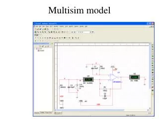
Multisim model
Multisim model. Noise sources. Resistors R1 and R2 (10 k ) Noise = 4R kT BW = 4(10.000)(1.38 10 -23 J/K)(295 K)(1 Hz) = 1.6 10 -16 V 2 Low pass filters f R1 = 1/2R1C2 = 1/2 (10.000 )(1.5 10 -12 F)=10.6 MHz f R2 = 1/2R2C1 = 1/2 (10.000 )(10 10 -9 F)=1.6 kHz Diode noise

Multisim model
E N D
Presentation Transcript
Noise sources • Resistors R1 and R2 (10 k) • Noise = 4R kT BW = 4(10.000)(1.38 10-23 J/K)(295 K)(1 Hz) = 1.6 10-16 V2 • Low pass filters • fR1 = 1/2R1C2 = 1/2 (10.000 )(1.5 10-12 F)=10.6 MHz • fR2 = 1/2R2C1 = 1/2 (10.000 )(10 10-9 F)=1.6 kHz • Diode noise • Dark current 1nA (use 180 G on –180V) • Diode capacity 10 pF • Amplifier noise • Use pspice amplifier model • Includes 1/f noise, etc.
Results 1/f Affected by C Noise R2 Noise R1
Summary • Calculation includes relevant sources • Si sensor 10 pF on –180 V with 1 nA dark current • Repeat for • InGaAs with 60 pF and –10 V bias • Amplifiers: • OPA847 • OPA 657 • ADA 4899-1 • Agilent 4395A • Use other software e.g. Tina-TI