BECHTEL ENGINEERING AE REVIEW
620 likes | 939 Vues
BECHTEL ENGINEERING AE REVIEW. BECHTEL ENGINEERING AE REVIEW. INTRODUCTION. Introduction. Why now? New Market (sort of) Standardize the “Bechtel Product” Ensure Common understanding between Bechtel Chiefs, Market Engineering and AEs Focus on Deliverables and Bechtel’s Standards

BECHTEL ENGINEERING AE REVIEW
E N D
Presentation Transcript
BECHTEL ENGINEERING AE REVIEW INTRODUCTION
Introduction • Why now? • New Market (sort of) • Standardize the “Bechtel Product” • Ensure Common understanding between Bechtel Chiefs, Market Engineering and AEs • Focus on Deliverables and Bechtel’s Standards • Understand how Bechtel documents should be used • Specifications and Guides • Model drawings • Standard notes and details
Safety ACCIDENTS • Top Three Accidents • Eyes on Path / Work (23%) • Body Mechanics (22%) • Line of Fire (15%)
Introduction • Functional Management • Duff Armstrong – Site Development Manager 925-983-8623 dcarmst@bechtel.com • Julie Furukawa – Site Acq Manager 925-983-2307 jfurukaw@bechtel.com • Gerry Moellenkamp – Engineer Manager 925-983-4336 gemoelle@bechtel.com • Tewfik Boutaleb – Market Lead Engineer 925-983-4336 tboutale@bechtel.com • Hawley Lowe – Records Lead 925-983-2309 hlowe@bechtel.com
Introduction • Contracts Team • Rudy Molvizar – Subcontracts Manager 925-983-2350 rmolviza@bechtel.com • Jennifer Alexander – Subcts Administrator 925-983-2340 jalexand@bechtel.com MT2, Trillium, Apex • Adam Campbell – Subcts Administrator 925-983-4350 accampbe@bechtel.comJRA, DCI Pacific, PDC, TRK • Jarrette Thompson – Subcts Administrator 925-973-2311 jdthomps@bechtel.comDelta, SAC
Introduction Deliverables The Primary Method to communicate all Deliverables is via eRoom. In some instances, hard copy is required
BECHTEL ENGINEERING AE REVIEW Contract Documents
Contract Documents (Engineering) • Quality Plans • All Subcontractors of Bechtel are required to have Quality plans submitted and approved by Bechtel • Waived if Subcontractor is ISO 9000 certified • Can provide their own • Use Bechtel’s pro-forma plan • Exhibit D • Scope of Work • Outlines what Bechtel expects of our Subcontractors • Exhibit E • List all Bechtel supplied supporting documentation that forms part of the contract.
Exhibit D • Exhibit D Defines the AE Scope of work • Highlights: • Section 1.3 CONTRACTOR developed Materials • “These documents were developed to assure quality and provide a consistent standard design in every market. The SUBCONTRACTOR shall use these documents and information to the maximum extent possible….” • “CONTRACTOR may revise the standard documents as the need arises, and the SUBCONTRACTOR shall be furnished with the revisions, and shall be required to use the latest revisions at all times.” • Repeated many times throughout the contract • Design Visits included in contract price. SUBCONTRACTOR is expected to visit the site to obtain the information they need.
Exhibit D • Highlights (Continued): • Section 2.3.3 • “Sample drawings listed in Exhibit “E” shall be used to establish the organization and the levels of details for the preparation of construction drawings.” • Section 2.3.6 • “Seismic requirements for equipment bracing and or anchorage shall be taken into consideration for the zone in which the site is located, complying with the seismic provisions of the applicable codes and standards when preparing construction drawings. Calculations sealed, signed and dated by a Licensed Professional Engineer in the state where the site is located shall be included with the drawings reflecting the design requirements.” • Section 2.10 Structural Analysis of Buildings • Subcontractor to Analyze building and Foundation • If the analysis shows a modification will be required, SUBCONTRACTOR must obtain approval to proceed with the design • Client or Contractor may opt to alter the configuration or move the site altogether • “Calculations shall be prepared in accordance with the calculation and software specification which is part of their scope of work, listed in Exhibit E and attached.”
Exhibit D • Highlights (Continued): • Section 2.14 Tower/Monopole Structural Analysis • Similar process and requirements as above • Must include Tower and Foundation • ALL electronic drawing files submitted to Contractor shall be “stand-alone”, with no reference files attached. • If they use xref files, be sure they are imbedded into the DWG files before submitting. • Section 3.1.2 • CONTRACTOR shall provide the drawing format, title block, and drawing and document numbering convention to SUBCONTRACTOR. Drawings shall be marked with an alpha character starting with Rev. A, when “Issued for Review” and a numerical character starting with Rev. 0, when “Issued for Construction or Permitting”. Alpha revisions shall be removed from the Revision Block when numerical revisions are issued. • Drawing Revisions • Except when an obvious revision to the scope is encountered, drawings shall remain ALPHA revisions until the CONTRACTOR advises that the drawing is fully corrected and may be given Rev 0 status.
Exhibit E • Exhibit E is part of the Contract • Section 1.0 General • “The work shall conform to and be performed in strict compliance with the following drawings and reference documents,…….” • Section 2.0 Samples • Lists the sample drawings sets to be used as guidance • Section 3.0 Reference Drawings • Standard Notes, symbols and Details • Section 4.0 Technical Specifications and Reference Documents • All listed documents form part of the contract • Two parts, Engineering and Construction • For AEs the Construction part is reference for you to know. It is aimed mainly at the General Contractors.
Standard Notes, Symbols and Details • Supplied in both PDF and DWG formats • Incorporate Bechtel and AT&T contract requirements • PDF versions for reference by most people • DWG formats are to be pasted into drawings by AE and used AS IS. • Changes to the details can only be made By Bechtel • No need to redraw, just cut and paste • DWG files have only TWO levels - Border and the detail • If there is something you don’t agree with, tell us. • Use Bechtel Standard Notes such as Detail #1000, 1011, 1020 and others. • Use of an AE’s own notes should be restricted as they may conflict with our Construction Terms and Conditions.
Standard Notes, Symbols and Details • Complete Index is supplied for help in finding Details • Series 1000 • Miscellaneous Notes • Series 1100 • Equipment Details • RRU, RRH, Power Plants, Raycap, etc • Series 1200 • Civil Engineering Details • Concrete slabs, Gravel Access Drive, Silt Fence etc • Series 1300 • Structural Details • Series 1400 • Electrical Details • RF Interconnects, Alarm wiring, DC and Fiber cabling
Standard Notes, Symbols and Details • Series 1500 • Antenna Details • Series 1700 • Equipment details (ran out of space with 1100 series) • All similar details are grouped together • Example • 1400 is a system diagram showing Baseband unit and the RRH/RRU interconnection diagrams • All similar drawings are numbered 1400a to 1400f • A complete Revision history follows the index • No need to check through all the details to see what has changed since the last revision
Drawing Deliverable Duration Expectations • RFDS to Design Visit 7 – 14 Days • Design Visit to 90% Rev A Zoning Drawings 7 Days • 90% ZDs Rev A Redlines for Next Revision 3 Days • CDs to 90% Rev A after Zoning Approval 5 Days • 90% CDs Rev A Redlines to Next Revision 3 Days
BECHTEL ENGINEERING AE REVIEW Civil/Structures Specifications
Partial List of Specifications • List Title • 3GS-T18-00003 Tower Mapping, Analysis and Repair • 3GS-T18-00011 Monopole Reinforcement Systems and New Ports • 3GS-T18-00012 Design Calculations and Software • 3GS-T18-00013 Adhesive and Mechanical Anchors - New
3GS-T18-00003 Tower Mapping, Analysis and Repair • Provides guidelines for Mapping a Tower in order to perform an accurate structural analysis. • Only used when drawing information is not available or it is incomplete or unavailable • Analysis of coax should match actual placement on tower. • Statements such as “coax assumed to be equally distributed on each tower face” are not acceptable. • Mapping includes the Foundation. Dispersion wave technology is good system for foundation mapping. • Mapping sample sheets are in the back of the specification.
3GS-T18-00003 Tower Mapping, Analysis and Repair • Provides guidelines for Modifying a tower • Fixes to develop full load path. • On SST legs, additional members added to legs to be welded to splice plates at either end. • Clamp on members do not help unless they go to both ends. • Monopoles • Additional members, plates or shapes to build up section • modulus to go to base plate for continuity. • Splices are needed for continuity. • For more details on monopole repairs see 3GS-T18-00011
3GS-T18-00003 Tower Mapping, Analysis and Repair • Guyed Towers • Add struts to reduce unbraced length of members • Change out guys to redistribute loads • Foundation Repairs • Anchor Blocks – add on to ends so soil in front of anchor block is not disturbed • Caissons – Add collars to increase area and Section Modulus
3GS-T18-00011 Selection, Purchase and Installation of Monopole Reinforcement Systems and New Ports • Conventional Fixes – utilize plates or structural shapes that are bolted or welded to the shaft intermittently to add section modulus to the pole. • Blind Bolts – qualified by the manufacturer and approved by Bechtel prior to use • Specify the use of LOW HEAT WELDING • Procedures to protect the cable inside.
3GS-T18-00011 Selection, Purchase and Installation of Monopole Reinforcement Systems and New Ports • Adding additional ports to existing pole – follow original pole fabricator’s procedures for installing port. • Nonconventional Systems – see section 1.6 of the Specification for a listing of systems to be approved by engineering before they are installed. • Unacceptable Systems – those that use adhesives and/or carbon fiber plates
3GS-T18-00012 Wireless Site Facilities Structural Analysis and Design Calculations and Software • Structural Analyses to be complete • Towers – foundations as well as superstructure • Buildings – existing building checked for additional load as well as the communications feature on the roof or wall. • Map if existing drawings are not available. • Structure Shop Drawings, Foundation Drawings, Tower Inventory Report, Geotechnical Report, Foundation Map and /or Tower Superstructure Map and Existing Structure/Foundation Calculations to be attachment to calculation, not just referenced. • Calculations originated, checked and approved. Does not have to be three people but should be at least two people to demonstrate ownership and validation.
3GS-T18-00012 Wireless Site Facilities Structural Analysis and Design Calculations and Software • Calculations shall be orderly and complete. The body of the calculation shall include the following items: • Calculation Cover Sheet • Table of Contents • Purpose • Assumptions • References • The Calculation content shall include: • Numerical calculations • Equations shall be identified as to their source • Calculations must be clear enough to validate • Conclusion • PE Seal, Signature, Date
3GS-T18-00012 Wireless Site Facilities Structural Analysis and Design Calculations and Software • Proprietary software to be VALIDATED. • This requires comparison with: • A hand calculation • A comparable industry recognized program • Published and current experimental or operational data • Applicable empirical data and information from technical literature • Validation to be contained in a Verification Report.
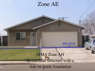
3GS-T18-00012 Wireless Site Facilities Structural Analysis and Design Calculations and Software • Types of Sites • Existing Towers – analyze Superstructure and Foundation. • New Towers – Calculations are done by the Fabricator. • Rooftops – analyze platform/mount and Building Load Path to supporting soil. • Tenant Improvement – check existing floor structural members and Building Load Path to supporting soil. • Slabs – design and analyze for bearing, bending, shear, sliding, uplift and overturning. Can be a generic calculation.
3GS-T18-00012, Wireless Site Facilities Structural Analysis and Design Calculations and Software • QMS – Quality Management System submitted one time, not with each calculation. QMS is evidence of established procedures • COA – Business to have current COA to practice engineering in a the state • ERC – Engineer in Responsible Charge. Typically a state rules requirement. • Licensed PE to seal all Drawings and Calculations.
3GS-T18-00013 Selection, Inspection and Testing of Hilti Adhesive and Mechanical Anchors for Wireless Site Facilities • AE and Anchor Installers require training by the anchor manufacturer. • Select anchor that is appropriate for the material it is going into. • Anchors designed in accordance with requirements of the appropriate Codes, ESR’s, Manufacturers Recommendations and Authority Having Jurisdiction. • AE specify Special Inspection and Special Testing in accordance with the ESRs and Chapter 17, typically, of the UBC 1997, IBC 2000, 2003, 2006, 2009, IEBC, ICBC, etc.
BECHTEL ENGINEERING AE REVIEW Design Review Process
Design Review Process Requirements • Market Engineers will review all drawings in Market • AE is required to include the AE Review Status Stamp on the front page of the drawing set.
Bechtel Design Review • The first edition of any Drawing is issued as REV A “For Review” • Bechtel Market Engineer will review the drawing and redline any changes • Redline is sent back to the AE • AE will correct any issues with the drawing and return to Bechtel as REV B. • Do not go to Rev 0 until instructed in writing in the AE Review Block • Once Rev 0 drawing is issued, Bechtel is allowed one revision to incorporate Client/Landlord/Jurisdiction comments • After Rev 1 all changes are at extra cost to Bechtel unless changes requested to Rev 0 were incorrectly done. • SCOPE CHANGES WILL BE COMPENSATED
Design Review Process - DRN • DRN Process with Bechtel PMO • Primarily an internal Bechtel process • Sample of work is reviewed by the Chief Engineers or their designates • Monitors compliance with Bechtel design requirements • Affects Bechtel’s AE Subcontractors • TWO of each deliverable type (drawings, calcsetc) are initially submitted for review. • Chiefs give comments and A, AC, NA status • Any NA status requires submission of additional deliverables until 2 consecutive A or AC documents have been received.
Re-occurring Technical Issues • Continued problems with lack of attention to details • Same issues are repeated time and time again on new drawing sets • Missing tower foundation analysis with Tower Structural • Specified or validated software not used • Not using Bechtel standard details, format and detail numbers • Rooftop platform calculations do not include building structure adequacy assessment • Anchorage details not included in drawings. Calculations to support them not provided at CONTRACTOR request. • Documents not PE sealed, signed and dated (unless specified otherwise by CONTRACTOR).
Re-occurring Technical Issues • Out of date revisions of Standard Notes and Details being used • Details from older Bechtel contracts being used • Missing Electrical details • Power panel schedule missing • Missing RF interconnection details (1400 series)
BECHTEL ENGINEERING AE REVIEW Electrical Design Guidance
Standards, Codes and Practices • NEC (NFPA70) National Electric Code • Version accepted by the Jurisdiction where the site work is taking place. • NFPA 780 Standard for Installation of Lightning protection Systems • NESC National Electric Safety Code • For installations in and around Power installations • IEEE 80 Guide for Safety In Substation Grounding • For sites at or directly adjacent to Substations only • Bechtel does not require compliance at tower sites unless Utility does. • IEEE 81 Measuring Earth Resistivity • ANSI J-STD-607-A Commercial Building Grounding • AT&T Grounding and Bonding Standard ATT-TP-7646
Bechtel Standards • Bechtel Standard Notes and Details Rev 1 • 25736-000-A3J-00000-00001 Rev 1 • Technical Specification for Design and Testing of Facility grounding for Cell Sites • 25736-000-3PS-EG00-0001 Rev 0 • Model Site Drawings • Site Drawing Samples present general content expectations • Part of Exhibit E • Electrical Service Assessment and Evaluation Guideline • 25736-000-3DJ-GEX-00003 Rev 0 • AC Power Panel Schedule Guideline and Spreadsheet • Provided by Bechtel
Grounding Issues • Recurring items to be aware of: • Far too many ground rods indicated • Missing Buried Ground Rings (BGR) • Connections to Fence posts not shown • Requires bonding corner posts, Gate posts and Gates • Also requires any metallic object within 6’ of BGR to be bonded to the BGR • Fence post within 6 foot distance must all be bonded to the BGR • Bonds to Existing BGR improperly made • 2 bonds must be made between the TOWER ground ring and the equipment ground ring • Bonds may not be made to existing equipment ground rings of other carriers even if they are closer • Rod spacing should ideally be 2 times the length of the rod but NO less than 1 times the length • See Bechtel Details 1213 and 1214
Tower Grounding Considerations • ANSI/TIA 222 Rev G considerations for new Towers • Tower Buried Ground Ring (BGR) must now be 2/0 AWG wire • Ground rods must be a minimum of 10’ instead of 8’ • Bonding wires to the tower base must also be 2/0 AWG • All Towers must have a minimum of THREE bonds to the Tower BGR. For Self supports it requires one per leg. • Does NOT apply to equipment pad ground rings. 2 AWG is fine. • Requires Soil PH value in particular for Guy wire installations to determine if extra effort is required to protect Guy wires from corrosion at the Anchor points. • Existing ground rings do not need to be upgraded.
AC Power Panels and Loading • All Sites where new AC connections are being made shall have a Power Panel Schedule with load calculations included with the design documents. • Bechtel can provide an Excel spreadsheet to assist in the calculation • All Rectifiers are to be considered as non-continuous loads • All Air Conditioners are continuous loads unless the controls do not allow units to operate simultaneously. • Heaters are continuous loads unless they never operate at the same time as the Air Conditioners. If they do not, then the larger load of the two shall be deemed continuous • AC powered BTS are not considered Continuous • Tower lighting is a continuous load • LCL (Largest Continuous Load) is not in NEC as part of load calculations.
BECHTEL ENGINEERING AE REVIEW Interface Procedure
Change Order Process • Issued only by Bechtel Contracts!! • No work is authorized unless a Change order is issued • Any work done without a CO is done at risk • Engineers are not allowed to authorize work • Includes overtime, scope changes, extra drawing sets • Scope changes will be directed by change order
Bechtel Standard Document Numbers (SDN) • Drawing must be numbered according to SDN • File names must follow SDN • 25736-635-LO(-T5-T4)-CCL00158-IFC-Rev A • (-T5-T4) identifies other scopes this drawing applies to. Do not include the parentheses. • Be sure the correct Charge code is used: • 25471-630 = Turf 1.0 • 25736-635 = Turf 2.0 • If you are not sure which one to use – ASK! • Using the wrong Identifiers could result in the drawing being returned for correction.
Document Control Procedures • AE Contractor Submittal Process Send email notification along with Transmittal only: To: Connorca@bechtel.com ATT.norcal@bechtel.com CC: Contract Administrator Engineer Subject Line: eRoom Upload Site Number Company Name Zip together Transmittal & Documents • Create Transmittal Documents • Name Documents • Upload to Bechtel eRoom • Copy/Paste zip file into ‘TO: Bechtel’ Bechtel DCC downloads AND routes to Field Coordinators Rev. 0