Download
1 / 9
90 likes | 225 Vues
2010-04-08 LEPP meeting Dan Peterson ILC highlights : Development of a TPC for the ILD detector at the ILC There are some significant differences between an e + e - experiment (ILC, CESR, LEP) and a pp experiment (LHC).

E N D
2010-04-08 LEPP meeting Dan Peterson ILC highlights : Development of a TPC for the ILD detector at the ILC There are some significant differences between an e+e- experiment (ILC, CESR, LEP) and a pp experiment (LHC). At the ILC, the reduced noise in the detector opens tracking options that are not possible at the LHC; ILD uses a TPC. (OK, Alice uses a TPC, but that is different.) The experiments drive the detector requirements; measurement of the recoil mass of l+l- in (e+ e- HZ, Z l+l-) drives the resolution; particle Flow Analyses requires a hermitic detector (98%). I will touch on the reasons for what we (LCTPC collaboration) are doing. Then describe the “highlights” what I have been doing this year.
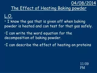
ILC TPC Large Prototype The International Linear Collider (ILC) is planned for commissioning inafter 2015. Electron-positron collisions will have 500GeV c.o.m. energy. One of the two certified detectors employs a Time Projection Chamber (TPC) for recognizing tracks and measuring the momentum. Detectors, like the ILD are being planned by international collaborations. A “large prototype”, representing a small section of the final TPC, will be operated in 2008-2009 (2009 – 2011). (from a poster for “graduate student night” 2006)
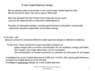
The Cornell group built the endplate for the TPC large prototype. Current work is an extension of the previous endplate development. 30-October-2008, Endplate, fully assembled, with Micromegas module in center location. 30-October-2008 The leak test, on the field cage: With 42 o-rings, and 8 pipe threads, the leak test passed. (from a presentation at a Linear Collider workshop, 2008-11-15 )
measure the mass recoiling againstl+l- in (e+ e- HZ, Z l+l-) δPt / Pt2 = 2 x 10⁻⁵ /GeV recoil mass resolution is dominated by other effects δPt / Pt2 = 4 x 10⁻⁵ /GeV recoil mass resolution is starting deteriorate δPt / Pt2 = 7 x 10⁻⁵ /GeV recoil mass resolution is dominated by momentum resolution (from a Journal Club, 2006-January ) Meeting the resolution goal δ(1/Pt) < 3 x 10⁻⁵ / GeV requires a point resolution of ~100μm, but more importantly, requires a knowledge of the magnetic field ∫ δ(Br) dz ~ 20 μm construction can deliver ~20 mm (not μm), mapping can deliver ~2 mm. The improvement must come from track-based magnetic field calibration. For magnetic field calibration to converge, we must have a non-track-based calibration of the detector positions ~ 50 μm. We must have the stability of the detector positions ~ 50 μm
(from a Journal Club, 2006-January ) There are processes where WW and ZZ must be separated without beam constraints (example e+e- nnWW, nnZZ ). Particle Flow Analysis provides must jet energy resolution of about dE/E = 30% / E1/2 The energy resolution goal of the Particle Flow Analysis constrains the material in the endplate of the TPC, which is in front of the forward calorimeters. This is not the LHC; this is a 98% hermetic detector. At this time, the leading thought is that the material limit for the TPC endplate including structure, detector modules, electronics, and cooling, is 15% XO . That is a summary of our development goals: detector placement and stability at the level of 50 μm (achieved by the 2008 endplate) endplate material ~ 15% XO (not achieved by the 2008 endplate).
Progress this year has been in building and comparing CAD models of possible replacements for the current Large Prototype endplate, which will provide input for designing the ILD endplate. mass material deflection stress kg %X0 microns Mpa (yield: 241) LP1 18.87 16.9 33 1.5 Lightened 8.93 8.0 68 3.2 (all aluminum) Lightened Al 7.35 7.2 < 168* < 4.8* (Al-C hybrid) C 1.29 (* values for the aluminum only) Space-Frame 8.38 7.5 23 4.2 Material: space-frame has slightly more material than the Al-C hybrid. Deflection: space frame is more rigid than LP1, ~3x more rigid than the lightened (all Aluminum), and > 3x more rigid than the Al-C hybrid.
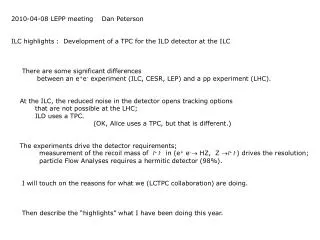
Space-frame model Lightened outer rim LP1 stiffening ring is removed. Cut-outs in radial machine tool direction leave material for strut mount. Lightened Uninstrumented Area 5mm thickness as in hybrid Sheet back-plane simple landing for strut mount removes adjustment of back-plane Between-Row Struts term change, these are now “struts” not the major load carriers in the ILD endplate and can be low density In-Row Struts major load carriers in ILD higher density Outer circumference struts termination as in ILD
Strut properties All struts are adjustable. All parts are Aluminum. Machined mount bolted to the front and back plates Adjustment screw 10-24 (m4.8-1.06) on one end 10-32 (m4.8-0.91) on the other end sensitivity is 150 micron/turn As modeled, the screw is 4mm, which is approximately the stress diameter. Spanning Rod As modeled, is 6mm solid, but could be 8mm hollow.
Deflection Maximum is 23 microns Back-plane locally warps ±5 microns The inside surface is smooth. Back-plane twists at 3-point intersections. This feature will carry over to the ILD. Not optimized: back-frame distance back-frame thickness vs strut density (spacing) strut thickness