Download
1 / 71
720 likes | 864 Vues
CIS 185 CCNP ROUTE Ch. 8 Implementing IPv6 – Part 3. Rick Graziani Cabrillo College graziani@cabrillo.edu Last Updated: Fall 2010. Materials. Book: Implementing Cisco IP Routing (ROUTE) Foundation Learning Guide: Foundation learning for the ROUTE 642-902 Exam By Diane Teare Book

E N D
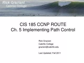
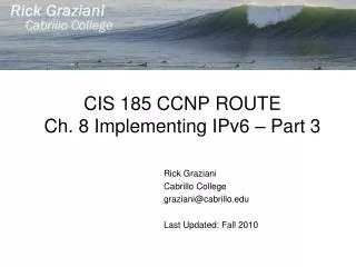
CIS 185 CCNP ROUTECh. 8 Implementing IPv6 – Part 3 Rick Graziani Cabrillo College graziani@cabrillo.edu Last Updated: Fall 2010
Materials • Book: • Implementing Cisco IP Routing (ROUTE) Foundation Learning Guide: Foundation learning for the ROUTE 642-902 Exam • By Diane Teare • Book • ISBN-10: 1-58705-882-0 • ISBN-13: 978-1-58705-882-0 • eBook • ISBN-10: 0-13-255033-4 • ISBN-13: 978-0-13-255033-8
Fortunately, the transition from IPv4 to IPv6 does not require upgrades on all nodes at the same time • IPv4 and IPv6 will coexist for some time. • There are many RFCs that relate to this transition
Techniques for the period of transition between IPv4 and IPv6: • Dual-stack techniques: • Hosts and network devices run both IPv4 and IPv6 at the same time. • Useful as a temporary transition • But has a lot of overhead and uses many resources. • Tunneling techniques: • Isolated IPv6 networks are connected over an IPv4 infrastructure using tunnels. • The edge devices are the only ones that need to be dual-stacked. • Scalability may be an issue if many tunnels need to be created. • Translation techniques: • A translator converts IPv6 packets into IPv4 packets and vise versa • Allows IPv6-only devices to communicate with IPv4-only devices. • Scalability may again be an issue because of the resources required on the translator device.
Transition methods between IPv4 and IPv6 • Dual-stack • Tunneling • Manual • Manual IPv6 Tunnel • GRE IPv6 Tunnel • Dynamic • 6to4 Tunnel • IPv4-Compatible IPv6 Tunnel (deprecated) • ISATAP Tunnel • Translation • Static NAT-PT for IPv6 • Dynamic NAT-PT for IPv6
Dual Stack • Integration method in which a node has connectivity to both an IPv4 and IPv6 network • Node has two protocol stacks. • A dual-stack node chooses which stack to use based on destination address: • Prefers IPv6 when available
IPv4: 10.10.10.1/24 IPv4: 10.10.10.2/24 R2 R1 IPv6: 2001:12::2/64 IPv6: 2001:12::1/64 R1(config)# inter fa 0/0 R1(config-if)# ip add 10.10.10.1 255.255.255.0 R1(config-if)# ipv6 add 2001:12::1/64 R1(config)# show ip interface fa 0/0 FastEthernet0/0 is up, line protocol is up Internet address is 10.10.10.1/25 Broadcast address is 255.255.255.255 <output omitted> R1(config)# show ipv6 interface fa 0/0 FastEthernet0/0 is up, line protocol is up IPv6 is enabled, link-local address is FE80::219:56FF:FE2C:9F60 Global unicast address(es): 2001:12::1, subnet is 2001:12::/64 Joined group address(es): FF02::1 FF02::2 <output omitted> • R1 is configured as dual-stacked. • FastEthernet 0/0 interface has two addresses on it: • IPv4 • IPv6 • For both protocols the addresses on R1 and R2 are on the same network.
IPv4: 10.10.10.1/24 IPv4: 10.10.10.2/24 R2 R1 IPv6: 2001:12::2/64 IPv6: 2001:12::1/64 • A drawback of dual stacking is the resources required within each device configured with both protocols. • The device must keep dual routing tables, routing protocol topology tables, etc.
Tunneling • Tunneling IPv6 Inside IPv4 Packets • This enables the connection of IPv6 islands without the need to convert the intermediary network to IPv6. • Tunnels can be either manually or automatically configured.
Isolated Dual-Stack • Tunneling can also be done between a host and a router, • The encapsulated tunnel connects the host to the edge router of the IPv6 network.
GRE IPv4 Header IPv6 Header Packet • Some tunneling terminology can be explained using this example: • IPv4 is the transport protocol, the protocol over which the tunnel is created. • IPv6 is the passenger protocol, the protocol encapsulated in the tunnel and carried through the tunnel. • Another protocol is used to create the tunnel, and is known as the tunneling protocol. • An example of such a protocol is Cisco’s Generic Routing Encapsulation (GRE) protocol. • Encapsulates the passenger protocol.
Translation A D IPv6 Network IPv4 Network 192.168.2.1 R1 2001:DB8:FFFF:1::1 192.168.30.1 Source Address: 2001:DB8:FFFF:1::1 Destination address: 2001:DB8:FFFF:FFFF::A Source Address: 192.168.2.2 Destination address: 192.168.30.1 NAT-PT • NAT-PT is a translation mechanism that sits between an IPv6 network and an IPv4 network. • The job of the translator (which of course can be a Cisco IOS router) is to: • Translate IPv6 packets into IPv4 packets and vice versa • More than an address translator: it is really a protocol translator.
Transition methods between IPv4 and IPv6 • Dual-stack • Tunneling • Manual • Manual IPv6 Tunnel • GRE IPv6 Tunnel • Dynamic • 6to4 Tunnel • IPv4-Compatible IPv6 Tunnel (deprecated) • ISATAP Tunnel • Translation • Static NAT-PT for IPv6 • Dynamic NAT-PT for IPv6
Manual IPv6 Tunnels • Simulates a permanent link between two IPv6 domains over an IPv4 backbone. • Physical interfaces may also be used as the tunnel source and destination interfaces, which also have IPv4 addresses. • Best practice is to use loopback interfaces • The end routers implementing a manual tunnel must be dual-stacked
Protocol 41 IPv4 Header IPv6 Header IPv6 Data 20 bytes IPv6 Manual Tunnel IPv6 Header IPv6 Header IPv6 Data IPv6 Data • Manually tunneling IPv6 inside of IPv4 uses IPv4 protocol 41 and adds a 20-byte IPv4 header (if there are not any options in the header) before the IPv6 header and payload (data).
Protocol 41 IPv4 Header IPv6 Header IPv6 Data 20 bytes • The IPv6 communication can be made secure with the use of IPsec: • Confidentiality • Integrity • Authentication
There are two IPv6 networks:, • 13::/64 and 24::/64 • Separated by an IPv4-only network. • IPv4 RIP is running between R1 and R2 to provide connectivity between the loopback interface networks. • Successful ping and a display of R1’s IPv4 routing table.
R1(config)# inter tunnel 12 R1(config-if)# no ip address R1(config-if)# ipv6 address 12::1/64 R1(config-if)# tunnel source loopback 101 R1(config-if)# tunnel destination 10.2.2.2 R1(config-if)# tunnel mode ipv6ip R2(config)# ipv6 unicast-routing R2(config)# interface tunnel 12 R2(config-if)# no ip address R2(config-if)# ipv6 address 12::2/64 R2(config-if)# tunnel source loopback 102 R2(config-if)# tunnel destination 10.1.1.1 R2(config-if)# tunnel mode ipv6ip • Objective is to provide full connectivity between the IPv6 islands over the IPv4-only infrastructure. • Since the tunnel does not have an IPv4 address, the no ip address command is used. • The appropriate loopback address is used as the tunnel source • Its IPv4 address will be the source address for the tunnel. • IPv4 is functioning here as the encapsulation protocol and as the transport protocol. • The tunnel destination is the IPv4 address of the other router. • The tunnel mode command defines the encapsulation; • Manual IPv6 tunnel with IPv6 as the passenger protocol
Shows the tunnel interface encapsulating the outgoing IPv6 traffic and decapsulating the return traffic. • The debug also indicates that an additional 20 bytes are being added to the packet; this is the IPv4 packet header.
R1# show interface tunnel 12 Tunnel12 is up, line protocol is up Hardware is Tunnel MTU 1514 bytes, BW 9 Kbit, DLY 500000 usec, rely 255/255, load 1/255 Encapsulation TUNNEL, loopback not set, Keepalive not set Tunnel source 10.1.1.1 (Loopback101, destination 10.2.2.2 Tunnel protocol/transport IPv6/IP • The tunnel mode is indicated in the “Tunnel protocol/transport IPv6/IP” line
The RIPng process RIPoTU will be enabled between: • R3 and R1 • R2 and R4 • IPv6 tunnel between R1 and R2 • The tunnel interface can participate in routing just like any other IPv6 link. • Notice that: • RIPng will run across the tunnel while • IPv4 RIP is running across the physical interfaces: to provide connectivity between the IPv4 addresses on the loopback interfaces.
R1(config)# ipv6 unicast-routing R1(config)# interface tunnel 12 R1(config-if)# no ip address R1(config-if)# ipv6 address 12::1/64 R1(config-if)# tunnel source loopback 101 R1(config-if)# tunnel destination 10.2.2.2 R1(config-if)# tunnel mode ipv6ip R1(config-if)# ipv6 rip RIPoTU enable R1(config)# interface fa 0/0 R1(config-if)# ipv6 add 13::1/64 R1(config-if)# ipv6 rip RIPoTU enable R1(config)# ipv6 router rip RIPoTU R1(config)# router rip R1(config-router)# network 172.16.0.0 R2(config)# ipv6 unicast-routing R2(config)# interface tunnel 12 R2(config-if)# no ip address R2(config-if)# ipv6 address 12::2/64 R2(config-if)# tunnel source loopback 102 R2(config-if)# tunnel destination 10.1.1.1 R2(config-if)# tunnel mode ipv6ip R2(config-if)# ipv6 rip RIPoTU enable R2(config)# interface fa 0/0 R2(config-if)# ipv6 add 24::2/64 R2(config-if)# ipv6 rip RIPoTU enable R2(config)# ipv6 router rip RIPoTU R2(config)# router rip R2(config-router)# network 172.16.0.0 R3(config)# ipv6 unicast-routing R3(config)# interface fa 0/0 R3(config-if)# ipv6 add 13::3/64 R3(config-if)# ipv6 rip RIPoTU enable R3(config)# ipv6 router rip RIPoTU R4(config)# ipv6 unicast-routing R4(config)# interface fa 0/0 R4(config-if)# ipv6 add 24::4/64 R4(config-if)# ipv6 rip RIPoTU enable R4(config)# ipv6 router rip RIPoTU • IPv4 RIP is running across the physical interfaces • On R1 and R2, RIPng is enabled on the tunnel interface and on the FastEthernet interface. • On R3 and R4, RIPng is only enabled on the FastEthernet interfaces.
R2# show ipv6 route rip R 13::/64 [120/3] via FE80::A01:101, Tunnel12 R4# show ipv6 route rip R 12::/64 [120/2] via FE80::2, FastEthernet0/0 R 13::/64 [120/3] via FE80::2, FastEthernet0/0 R3# ping 24::4 !!!!! R3# • To verify full connectivity across the tunnel, a ping from R3 to R4 is performed; as shown in the example it is successful.
Transition methods between IPv4 and IPv6 • Dual-stack • Tunneling • Manual • Manual IPv6 Tunnel • GRE IPv6 Tunnel • Dynamic • 6to4 Tunnel • IPv4-Compatible IPv6 Tunnel (deprecated) • ISATAP Tunnel • Translation • Static NAT-PT for IPv6 • Dynamic NAT-PT for IPv6
GRE IPv6 Tunnels • GRE IPv6 tunnels are very similar to manual tunnels. • GRE tunnels were developed by Cisco; • GRE encapsulation is the default tunneling protocol (configured with the tunnel mode command) on Cisco routers.
The communication can be made secure with the use IPsec. • GRE itself does not provide these security features; it is only an encapsulation protocol.
R1(config)# ipv6 unicast-routing R1(config)# interface tunnel 12 R1(config-if)# no ip address R1(config-if)# ipv6 address 12::1/64 R1(config-if)# tunnel source loopback 101 R1(config-if)# tunnel destination 10.2.2.2 R2(config)# ipv6 unicast-routing R2(config)# interface tunnel 12 R2(config-if)# no ip address R2(config-if)# ipv6 address 12::2/64 R2(config-if)# tunnel source loopback 102 R2(config-if)# tunnel destination 10.1.1.1 • Objective provide full connectivity between the IPv6 islands over the IPv4-only infrastructure. • The first step is to create a GRE tunnel between routers R1 and R2 • Notice that the configuration is identical to the manual tunnel configuration, with one exception: • tunnel mode command is not required since GRE is the default encapsulation (mode). • As before, as soon as the tunnel has been created, the tunnel interface comes up.
R1# show interface tunnel 12 Tunnel12 is up, line protocol is up Hardware is Tunnel MTU 1514 bytes, BW 9 Kbit, DLY 500000 usec, rely 255/255, load 1/255 Encapsulation TUNNEL, loopback not set, Keepalive not set Tunnel source 10.1.1.1 (Loopback101, destination 10.2.2.2 Tunnel protocol/transport GRE/IP • The encapsulation, source address, and destination address can all be verified with this command. • Confirmed that the tunnel mode is GRE (default).
To verify the tunnel operation, on R2: • debug ip packet detail enabled • Ping R1’s IPv6 address on the tunnel • The protocol of 47 is also displayed; this is the protocol number for GRE.
R1(config)# ipv6 unicast-routing R1(config)# interface tunnel 12 R1(config-if)# no ip address R1(config-if)# ipv6 address 12::1/64 R1(config-if)# tunnel source loopback 101 R1(config-if)# tunnel destination 10.2.2.2 R1(config-if)# tunnel mode R1(config-if)# ipv6 rip RIPoTU enable R1(config)# interface fa 0/0 R1(config-if)# ipv6 add 13::1/64 R1(config-if)# ipv6 rip RIPoTU enable R1(config)# ipv6 router rip RIPoTU R1(config)# router rip R1(config-router)# network 172.16.0.0 R2(config)# ipv6 unicast-routing R2(config)# interface tunnel 12 R2(config-if)# no ip address R2(config-if)# ipv6 address 12::2/64 R2(config-if)# tunnel source loopback 102 R2(config-if)# tunnel destination 10.1.1.1 R2(config-if)# tunnel mode R2(config-if)# ipv6 rip RIPoTU enable R2(config)# interface fa 0/0 R2(config-if)# ipv6 add 24::2/64 R2(config-if)# ipv6 rip RIPoTU enable R2(config)# ipv6 router rip RIPoTU R2(config)# router rip R2(config-router)# network 172.16.0.0 NOT configured for GRE R3(config)# ipv6 unicast-routing R3(config)# interface fa 0/0 R3(config-if)# ipv6 add 13::3/64 R3(config-if)# ipv6 rip RIPoTU enable R3(config)# ipv6 router rip RIPoTU R4(config)# ipv6 unicast-routing R4(config)# interface fa 0/0 R4(config-if)# ipv6 add 24::4/64 R4(config-if)# ipv6 rip RIPoTU enable R4(config)# ipv6 router rip RIPoTU • This is the same configuration used for the manual tunnel example, except: • no tunnel mode ipv6ip
The trace confirms the path is via the IPv6 tunnel network 12::/64.
IPV6 GRE Tunnel over IPv6 Tunnels – Read on your own • We now configure another tunnel, IPv6 GRE tunnel over IPv6. • Now - IPv6 is both the transport protocol and the passenger protocol • GRE is still the carrier protocol. • IPv6 packets are encapsulated in IPv6 packets. • This new tunnel is created between the physical interfaces on R3 and R4 • OSPFv3 is configured as the routing protocol over the tunnel • R3 and R4 (new) loopback interfaces are in separate OSPFv3 areas. • Notice that there is no direct physical connection between R3 and R4; • The GRE IPv6 tunnel is configured between R3 and R4, • but the physical path between these routers is still via R1 and R2 (and in the IPv6 world, this path includes the GRE IPv4 tunnel).
R3(config)# ipv6 unicast-routing R3(config)# interface tunnel 34 R3(config-if)# no ip address R3(config-if)# ipv6 address 34::34:4/64 R3(config-if)# tunnel source fa0/0 R3(config-if)# tunnel destination 24::4 R3(config-if)# tunnel mode gre ipv6 R4(config)# ipv6 unicast-routing R4(config)# interface tunnel 34 R4(config-if)# no ip address R4(config-if)# ipv6 address 34::34:4/64 R4(config-if)# tunnel source fa0/0 R4(config-if)# tunnel destination 24::4 R4(config-if)# tunnel mode gre ipv6 • Tunnel is created between R3 and R4, as shown in Example 8-110. • This configuration is very similar to the previous tunnel configuration. • The tunnel destination address is an IPv6 address instead of an IPv4 address • One difference is that instead of using the loopback interfaces as tunnel source and destination, the physical FastEthernet 0/0 interfaces are used • Although using loopback interfaces is a best practice (this was done to demonstrate that it can be done). • Another difference is that the tunnel mode gre ipv6 command is added, indicating that the GRE tunnel is over IPv6 as the transport protocol.
R3(config)# ipv6 unicast-routing R3(config)# interface tunnel 34 R3(config-if)# no ip address R3(config-if)# ipv6 address 34::34:4/64 R3(config-if)# tunnel source fa0/0 R3(config-if)# tunnel destination 24::4 R3(config-if)# tunnel mode gre ipv6 R3(config-if)# ipv6 ospf 1 area 0 R3(config)# interface loopback 103 R3(config-if)# ipv6 address 103::1/64 R3(config-if)# ipv6 ospf 1 area 33 R3(config)# ipv6 router ospf 1 R3(config-router)# router-id 3.3.3.3 R4(config)# ipv6 unicast-routing R4(config)# interface tunnel 34 R4(config-if)# no ip address R4(config-if)# ipv6 address 34::34:4/64 R4(config-if)# tunnel source fa0/0 R4(config-if)# tunnel destination 24::4 R4(config-if)# tunnel mode gre ipv6 R4(config-if)# ipv6 ospf 1 area 0 R4(config)# interface loopback 104 R4(config-if)# ipv6 address 104::1/64 R4(config-if)# ipv6 ospf 1 area 44 R4(config)# ipv6 router ospf 1 R4(config-router)# router-id 4.4.4.4 • Configure OSPFv3 on R3 and R4 • Notice that area 0 is between the routers on the tunnel interface • the loopback interfaces are in different areas (R3’s loopback is in area 33 and R4’s loopback is in area 44). • When the configuration is complete, the adjacency between the two routers goes to full state.
Transition methods between IPv4 and IPv6 Please read about Translation at the end of this chapter • Dual-stack • Tunneling • Manual • Manual IPv6 Tunnel • GRE IPv6 Tunnel • Dynamic • 6to4 Tunnel – Suggested Lab • IPv4-Compatible IPv6 Tunnel (deprecated) • ISATAP Tunnel • Translation • Static NAT-PT for IPv6 • Dynamic NAT-PT for IPv6
6to4 Tunnels • One of three automatic tunneling methods. • 6to4 tunnels are again used to connect IPv6 domains over an IPv4 network • They are point-to-multipoint, rather than the point-to-point tunnels discussed so far. • The 6to4 tunnels are built automatically by the edge routers, based on embedded IPv4 address within the IPv6 addresses of the tunnel interfaces on the edge routers.
The tunnel addresses are the concatenation of: • 2002 • Converted IPv4 address (172.16.101.1, 172.16.102.1) • A /128 prefix length was chosen in this example network. • These addresses will be configured as the IPv6 tunnel interface addresses • They embed the IPv4 addresses needed to establish the tunnel.
R1(config)# ipv6 unicast-routing R1(config)# interface tunnel 12 R1(config-if)# no ip address R1(config-if)# ipv6 address 2002:AC10:6501::/128 R1(config-if)# tunnel source loopback 101 R1(config-if)# tunnel destination R1(config-if)# tunnel mode ipv6 6to4 NOT configured R2(config)# ipv6 unicast-routing R2(config)# interface tunnel 12 R2(config-if)# no ip address R2(config-if)# ipv6 address 2002:AC10:6601::/128 R2(config-if)# tunnel source loopback 102 R2(config-if)# tunnel destination R2(config-if)# tunnel mode ipv6 6to4 NOT configured • Objective - provide full connectivity between the IPv6 islands over the IPv4-only infrastructure. • First step - Configure routers R1 and R2 so they establish the 6to4 tunnel between them. • Configuration is similar to the manual and GRE tunnel configurations. • One difference: tunnel destination is not specified • Because the destination IPv4 address is embedded in the IPv6 address. • Another difference is the tunnel mode ipv6ip 6to4 command is specified on each tunnel interface. As before, as soon as the tunnel has been created, the tunnel interface comes up.
Failed • To verify the tunnel operation: debug ipv6 packet detail and debug tunnel on R2 • R2: Ping R1’s IPv6 tunnel address • shows that the route is not found.
? Failed • Look at R2’s IPv6 routing table. • Notice that R2’s own tunnel address, 2002:AC10:6601::/128 is in the routing table, but R1’s address is not. • This is because the addresses assigned to the each end of the tunnel are on different subnets (recall that a /128 prefix length was used).
R1(config)# ipv6 unicast-routing R1(config)# interface tunnel 12 R1(config-if)# no ip address R1(config-if)# ipv6 address 2002:AC10:6501::/128 R1(config-if)# tunnel source loopback 101 R1(config-if)# tunnel mode ipv6 6to4 R1(config)# ipv6 route 2002::/16 tunnel12 R2(config)# ipv6 unicast-routing R2(config)# interface tunnel 12 R2(config-if)# no ip address R2(config-if)# ipv6 address 2002:AC10:6601::/128 R2(config-if)# tunnel source loopback 102 R2(config-if)# tunnel mode ipv6 6to4 R2(config)# ipv6 route 2002::/16 tunnel12 • To resolve this issue, a static route is configured on R2 to R1; on R1 to R2. • Since there is only one tunnel, the prefix length used on the static route is /16 • Results in any packets with a 2002 prefix being accessible via the tunnel.
The ping is tried again, and it is successful • This time the route is found, via the tunnel interfaces. • The debug output also shows the IPv4 addresses used for tunnel creation, extracted from the IPv6 addresses.
R1(config)# ipv6 unicast-routing R1(config)# interface tunnel 12 R1(config-if)# no ip address R1(config-if)# ipv6 address 2002:AC10:6501::/128 R1(config-if)# tunnel source loopback 101 R1(config-if)# tunnel mode ipv6 6to4 R1(config)# ipv6 route 2002::/16 tunnel12 R1(config)# ipv6 route 24::/16 2002:AC10:6601:: R2(config)# ipv6 unicast-routing R2(config)# interface tunnel 12 R2(config-if)# no ip address R2(config-if)# ipv6 address 2002:AC10:6601::/128 R2(config-if)# tunnel source loopback 102 R2(config-if)# tunnel mode ipv6 6to4 R2(config)# ipv6 route 2002::/16 tunnel12 R2(config)# ipv6 route ::/0 2002:AC10:6501:: • To reach destinations beyond the tunnel, more static routes must be added. • Notice that R1 gets to the 24 network via 2002:AC10:6601::, which is R2’s address. • On R2 A static default route can also be configured, to route for all destinations.
R1(config)# ipv6 unicast-routing R1(config)# interface tunnel 12 R1(config-if)# no ip address R1(config-if)# ipv6 address 2002:AC10:6501::/128 R1(config-if)# tunnel source loopback 101 R1(config-if)# tunnel mode ipv6 6to4 R1(config)# ipv6 route 2002::/16 tunnel12 R1(config)# ipv6 route 24::/16 2002:AC10:6601:: R1# show ipv6 route static S 24::/64 [1/0] via 2002:AC10:6601:: S 2002::/16 [1/0] via ::; Tunnel12 R1# ping 24::4 !!!!! R1 • As the routing table shows, it gets to anything that starts with 2002 via the Tunnel 12 interface. • Thus, R1 can reach network 24 via R2, which it reaches via the tunnel.
Transition methods between IPv4 and IPv6 • Dual-stack • Tunneling • Manual • Manual IPv6 Tunnel • GRE IPv6 Tunnel • Dynamic • 6to4 Tunnel • IPv4-Compatible IPv6 Tunnel (deprecated) • ISATAP Tunnel • Translation • Static NAT-PT for IPv6 • Dynamic NAT-PT for IPv6
Transition methods between IPv4 and IPv6 • Dual-stack • Tunneling • Manual • Manual IPv6 Tunnel • GRE IPv6 Tunnel • Dynamic • 6to4 Tunnel • IPv4-Compatible IPv6 Tunnel (deprecated) • ISATAP Tunnel • Translation • Static NAT-PT for IPv6 • Dynamic NAT-PT for IPv6
ISATAP Tunnels • ISATAP tunnels are very similar to 6to4 and IPv4-compatible IPv6 tunnels: • they all are used to connect IPv6 domains over an IPv4 network, • all embed an IPv4 address within the IPv6 address so that the tunnel destination IPv4 address is easily obtained by the devices at the end of the tunnel and it can therefore automatically create the tunnel. • ISATAP was designed to transport IPv6 packets within a site (hence the “intra-site” part of its name); it can still be used between sites, but its purpose is within sites. • The main limitation of ISATAP is that it does not support IPv6 multicast. This is not an issue for static routing or BGP (like 6to4 tunnels)
ISATAP tunnels use IPv6 addresses in the format shown in Figure 8-54; a 64-bit prefix is concatenated to a 64-bit interface ID in EUI-64 format. • The 64-bit IPv6 prefix can be any valid unicast prefix, including a global routable prefix, a link-local prefix, or even a 6to4 prefix. • The prefix should be selected according to the address plan for the network. • The upper 32 bits of the interface ID are 0000:5EFE, a reserved OUI value indicating an IPv6 ISATAP address. • The lower (least significant) 32 bits of the interface ID contain the IPv4 address of the interface (written in hexadecimal). T • his embedded IPv4 address is used to create the tunnel, similar to other mechanisms. • 172.16.101.1. From the earlier Figure 8-52, the hexadecimal equivalent of this address is AC10:6501. • Therefore the 64-bit interface ID would be 0000:5EFE:AC10:6501.