
94 GHz Switching Circulator
94 GHz Switching Circulator. Tracy Shain Ryan Nichols Daniel Komisar Andrew Gadbois Advisor: Prof. Paul Siqueira. Develops microwave components from 18 - 300 GHz in satellite and millimeter wave communication Industry leader in millimeter wave communication

94 GHz Switching Circulator
E N D
Presentation Transcript
94 GHz Switching Circulator Tracy Shain Ryan Nichols Daniel Komisar Andrew Gadbois Advisor: Prof. Paul Siqueira
Develops microwave components from 18 - 300 GHz in satellite and millimeter wave communication • Industry leader in millimeter wave communication • Corporate headquarters in Northampton, MA • Complete in-house machining and fabrication • Allowing full facility access and use of high frequency equipment
Example System:Continuous Transmission with Receiver Protection
Why W-Band? • Better resolution for remote sensing • Smaller • Higher bandwidth as percentage of center frequency
Design Responsibilities RF Design and Simulation Tracy Shain Research Daniel Komisar RF Measurements and Tuning Ryan Nichols Design of Driver Circuit Andrew Gadbois
Deliverables • Design plans • Junction schematics from HFSS simulation • Driver circuit schematics from simulations • Material and spacial tolerances • Test results/Final specs • Empirical tuning instructions • 94 GHz switching circulator
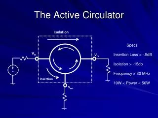
Specifications • Bandwidth: 3% • Center Frequency: 94 Ghz • Isolation: 20 dB • Insertion loss: 0.8 dB • VSWR: 1.3:1 • Switching Time: 10 ns • Temp: -40°C – 85°C • Driver circuit CMOS/TTL compatible
Design Alternatives Types of Switches: Ferrites PIN Diode Mechanical Transmission: Waveguide Microstrip
DesignAlternatives Types of Latching: • No Latching • Requires constant power to maintain magnetic fields • Eg. Electromagnet with no field when there is no current • Half - Latching • Constant field in one direction, but requires constant power to reverse field • Fully - Latching • Short pulse of current in one direction is capable of rearranging the fields within the ferrite to reverse the direction of the magnetic field
Critical Analysis of Failure • Insertion loss • Frequency response • Power handling • Input/output impedance • VSWR • Magnetic Leakage
Schedule January
MDR Specifications • Complete Ferrite research • Order material to allow sufficient lead time • Complete microwave design and numerical tests - Ansoft Design and Simulation - Analyze 2 Design Alternatives - Test 94 Ghz Y-Junction Waveguide • Preliminary Driver Design


![Frequency [GHz]](https://cdn1.slideserve.com/3024092/slide1-dt.jpg)


![Frequency [GHz]](https://cdn3.slideserve.com/6756635/slide1-dt.jpg)