Magnetization Current in a Real transformer
Magnetization Current in a Real transformer. Although the output of the transformer is open circuit, there will still be current flow in the primary windings Magnetization current, i M Core-loss current, i h+e. The relation between current and flux is proportional since.

Magnetization Current in a Real transformer
E N D
Presentation Transcript
Magnetization Current in a Real transformer • Although the output of the transformer is open circuit, there will still be current flow in the primary windings • Magnetization current, iM • Core-loss current, ih+e The relation between current and flux is proportional since
Magnetization Current in a Real transformer Therefore, in theory, if the flux produce in core is sinusoidal, therefore the current should also be a perfect sinusoidal. Unfortunately, this is not true
Magnetization Current in a Real transformer • current in a transformer has the following characteristics: • It is not sinusoidal but a combination of high frequency oscillation • The current lags the voltage at 90o • At saturation, the high frequency components will be extreme
Magnetization Current in a Real transformer • Core-loss current: • Eddy current loss> Eddy current is dependent upon the rate of change of flux • Hysteresis loss > a non linear loss At no-load, the primary windings is known as the excitation current
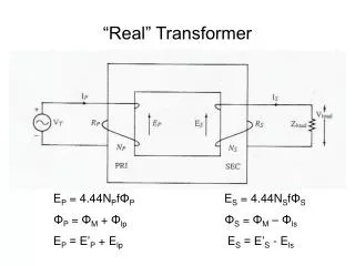
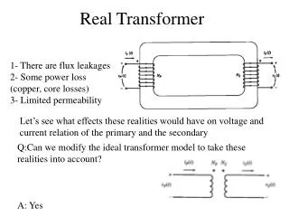
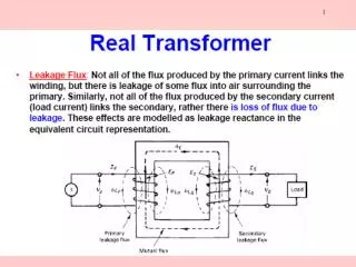
Magnetization Current in a Real transformer The equivalent circuit of a transformer Taking into account real transformer, there are several losses that has to be taken into account in order to accurately model the transformer, namely: 1- Copper (I2R) Losses 2- Eddy current Losses 3- Hysteresis Losses 4- Leakage flux
Equivalent Circuit a) referred to primary side b) referred to secondary side
Approximate equivalent circuit Approximate equivalent circuit c) Referred to primary side (no exicitation) d) Referred to secondary side (no excitation).
Example 3 A not-quite-ideal transformer having 90 turns on the primary and 2250 turns on the secondary is connected to a 120 V, 60 hz source. The coupling between the primary and the secondary is perfect but the magnetizing current is 4 A. calculate: • The effective voltage across the secondary terminals • The peak voltage across the secondary terminals. • The instantaneous voltage across the secondary when the instantaneous voltage across the primary is 37 V. Ans: 3000V, 4242 V, 925 V.
Example 4 An ideal transformer having 90 turns on the primary and 2250 turns on the secondary is connected to a 200 V, 50 Hz source. The load across the secondary draws a current of 2 A at a power factor of 80 per cent lagging. Calculate : • The effective value of the primary current • The instantaneous current in the primary when the instantaneous current in the secondary is 100 mA. • The peak flux linked by the secondary winding. Ans: 50 A, 2.5 A, 10 mWb.
Example 5 Calculate voltage E and current I in the circuit of Fig. shown below, knowing that the ideal transformer T has a primary to secondary turns ratio of 1;100. Ans: 800 V, 2 A.
Determination of transformer parameters: Open Circuit Test Total excitation admittance, YE = GC - jBM The magnitude of the excitation admittance (referred to primary), The angle of the admittance ,from the circuit power factor. The power factor is always lagging for a real transformer. Hence, Hence
Determination of transformer parameters: Short Circuit Test • Magnitude of series impedance: • Power factor:
Three Phase Transformer • Three phase transformer consists of 3 transformers. • It is connected independently or in combination of 3 transformers. • Primary and secondary windings can be connected as wye (Y) or delta (∆) • Thus, there are 4 types of connections: • Wye – wye (Y-Y) • Wye – delta (Y-∆) • Delta – wye (∆-Y) • Delta – delta (∆-∆)
The autotransformer • On some occasions it is desirable to change voltage levels by only a small amount. A special-purpose transformer, called an autotransformer, is used in these cases. The voltages in the coils are related to the voltages at the terminals by the Equations And the currents in the coils are related to the currents at the terminals by the equations the relationship between the two sides of an autotransformer
3 phase Transformer 3 phase transformer connected independently
Three Phase Transformer Three phase transformer connected to a common core with three legs
Connection Y-Y Three Phase transformer Y-Y connection
Three-phase transformation using two transformers In addition to the standard three-phase transformer connections, there are ways to perform three-phase transformation with only two transformers Some of the more important two-transformer connections are 1. The open- Δ (or V-V) connection 2. The open-Y-open- Δ connection 3. The Scott-T connection
Instrument transformers Instrument transformers are small transformers intended to supply low values of current and voltage to measuring instruments and protective relays. Current transformer (CT)> used in measurement of high current 1. It’s a step up transformer 2. Secondary side is usually rated up to 5 A 3. Primary circuit have few turns Potencial transformer (CT) > used in measurement of high voltage 1. It’s a step down transformer 2. Secondary side is usually rated 110 V