V B
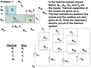
Draw equivalent electric circuit of a thermal system with rooms & inputs. Model DC motor system including motor torque & damping constants.

V B
E N D
Presentation Transcript
Problem 1: R1a In the thermal system shown below, Qk1, Qk2, Qk3 and TB are the inputs. Thermal capacities of the rooms are given as Ci. Thermal resistances between the rooms and the outdoor are also given as Ri. Draw the equivalent electric circuit of the thermal system. TA R3B C1 C2 C1 C3 RBa R3a R3B RBa R1a R2a R23 R12 Qi C2 TB R12 C3 R3a R2a R23 Qk1 + VB o o o - Qk3 Qk2 VA o o o ThermalElec. Ri Ri Ci Ci Ti Vi
(Rigit shaft) z1 For shaft 2: By 4 3 Jm , Bm JL 2 1 2 B + Vk K2 Motor - z2 Ra , La Ki , Kb : Motor armature current F r 7. Modeling of Electromechanical Systems Example 7.1 System including DC Motor K2 : Rotational rigidity of shaft 2 Ra : Motor winding resistance La : Motor winding inductance l: Length of the rotor windings Jm : Motor mass moment of inertia Bm : Motor rotational damping constant Ki : Motor torque constant Kb : Counter-electromotive force constant Vk : Motor voltage JL : Mass moment of inertia of the load By : Rotational damping constant of bearing Counter-electromotive voltage Motor torque
(Rigit shaft) z1 Shaft 2: By 4 3 Jm , Bm JL 2 1 2 + Vk K2 Motor - z2 Ra , La Ki , Kb Energy expressions : Input: Vk ; Generalized variables (Outputs): qa, θm, θL
z1 By 4 3 Jm , Bm JL 2 1 2 + Vk K2 Motor - z2 Ra , La Ki , Kb
x(t) k/2 Movable, m R b/2 Vk - + fa(t) C k/2 b/2 Fixed Example 7.2 Capacitor with moving plate Inputs: Vk(t) and fa(t) Generalized variables: q(t) and x(t) System of Nonlinear Differential Equations: Solve with Runga Kutta method
R L(x) x(t) Vk - + m k b Problem 2: The core of the inductor moves with the x coordinate and the variation of the inductance is given by L(x). Find the mathematical model of the system. x(t) and q(t) are the generalized variables and Vk() is the input
R2 R1 k2 k1 fk b L(x1) m1 C(x2) Vk - + m2 x1 x2 Problem 3: fk(t) and Vk(t) are the inputs of the electro-mechanical system shown in the figure. q(t), x1(t) and x2(t) are the generalized variables. Find the mathematical model of the system.