Download
1 / 106
1.34k likes | 2.01k Vues
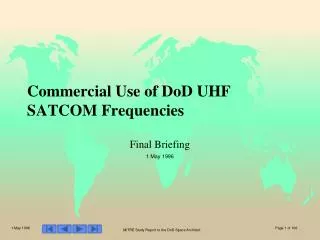
Commercial Use of DoD UHF SATCOM Frequencies. Final Briefing 1 May 1996. Commercializing UHF SATCOM Study Statement of Purpose. Analyze the opportunities and issues associated with opening up the UHF spectrum for commercial SATCOM use while preserving DoD assured access.

E N D
Commercial Use of DoD UHF SATCOM Frequencies Final Briefing 1 May 1996
Commercializing UHF SATCOM Study Statement of Purpose • Analyze the opportunities and issues associated with opening up the UHF spectrum for commercial SATCOM use while preserving DoD assured access
Top level Summary of Findings • A high capacity MEO system in the DoD UHF SATCOM band appears technically feasible and commercially viable • Moderate risks associated with design of UHF MBA satellite antenna and attractive Hand Held Terminal • A UHF MEO system appears more cost effective than replenishment of UFO • More channels per $ • Less expensive on a life cycle cost basis • Decision to buy commercial service versus acquisition of DoD owned system requires further study • Resolution of regulatory, legal, and business arrangement issues for spectrum sharing of UHF with commercial industry is a major challenge
Briefing Objective • Summary of regulatory issues • Technical tradeoff studies • Economic assessment • Legal aspects of spectrum contracting • Overall conclusions
Regulatory Issues Assured Access Trade Secondary Basis of UHF SATCOM
UHF Spectrum at a Glance ITU Table U.S. Table • ITU regulations give fixed and mobile terrestrial communications service prime use of the UHF spectrum internationally • UHF SATCOM use allowed on a non-interfering (secondary) basis internationally • Co-prime basis over US territory (restricted to DoD) • Italy, UK, NATO, and Russia also use UHF SATCOM 400 MHz Military Terrestrial Fixed & Mobile Service Primary Service Military Mobile Satellite Services** Mobile Satellite Services* 335 MHz Terrestrial Fixed & Mobile Service, broadcast, aeronautical radio-nav. aeronautical 322 MHz Military Terrestrial Fixed & Mobile Service, Military Mobile Satellite Services** Mobile Satellite Services* Mobile Satellite Services. 225 MHz *Secondary Service by Footnote 641 **Co-Prime by G100
UHF Spectrum Use US European • Air-ground-air, air-air and ground-ground communications • 25,000 aircraft HAVEQUICK radios • FAA control of military aircraft in national airspace • > 23,000 freq. assignments to federal agencies • Mobile satellite services • >10,000 UHF SATCOM radios • Unlicensed civil users (garage door openers, wireless security systems) • Operating under Part 15 of FCC Rules • Primarily military use by NATO nations • Heavy band use for: • air-ground-air ATC and military operations • radio relay (most of transportable/tactical nature) • mobile-satellite • aeronautical radio-navigation • broadcasting • Proposed European Table of Frequency Allocations increases mobile use of the bands, diminish fixed use • planned implementation by 2008
UFO Frequency Plan Gapfiller Narrowband Channels FLTSAT Wideband Channels FLTSAT Wideband Channels • 150 MHz of UHF spectrum • Projected L-band PCSsystems filed for 16.5 MHz • IRIDIUM received5.15 MHz • Odyssey received11.35 MHz • US UHF SATCOM frequencyplan provides ~4 MHz spread across 52 MHz in small non-contiguous chunks • A UHF PCS system will require an improved frequency plan 290 295 300 305 310 315 320 332 – 400 Uplink Frequency (MHz) Russian Allocation DSCS Broadcast Russian Allocation 240 245 250 255 260 265 270 Downlink Frequency (MHz) NATO IV Russian Allocation
Options for Making Commercial UHF SATCOM Viable • Negotiate change to ITU table that gives co-prime status to mobile satellite services in the UHF frequency band • Demonstrate that mobile satellite services are profitable even on a secondary basis • Show feasibility of interference mitigation techniques (spread spectrum or adaptive spectrum management) • Negotiate frequency plan with host nations • Trade UHF spectrum for assured access to the planned commercial SATCOM PCS systems • Include Allies and Russians in the plan
Potential Interference Mitigation Protocol • Scan frequency band for best quality channels using method similar to Orbcomm • Approximately 75 MHz available • Signal-to-noise measurement used to evaluate quality of current “best channels” • Terminal requests access and is assigned one of current “best channels” for conversation • Terminals stay on same channel until call completed or channel noise increases so that channel no longer among best • Terminals get new channel assignment • Buffer speech until switch completed • Potential to realize 16 MHz on an interference avoidance basis • Based on Orbcomm experience
Technical Tradeoff Study Objectives • DoD current/projected UHF system capabilities • Assessment of 7-beam constellations • Assessment of 19-beam constellations • Satellite MBA/payload sizing studies • HHT/antennas design studies • Gateway station design considerations
DoD Current UHF System Capabilities • Services provided • WBSV/NBSV • Text messages /file transfer • Facsimile/data base transfer • Intelligence broadcast • Terminal classes • Manpack/vehicular • Tactical airborne • Ship borne • Fixed sites • Intelligence broadcast receivers • No hand-held units
No. of 5KHz 25 KHz Total BW/ Total BW/ Total BW Sat. (NB) (NB) Satellite Footprint World Wide (KHz) (KHz) (KHz) UFO 8 21 17 530 1060 4240 No. of 5KHz 25 KHz Total/ Total/ Total Sat. (NB) (NB) Satellite Footprint World Wide 2 UFO 8 21 85 106 212 848 UFO System Capacity • UFO utilization is ≈1 MHz vs. 16.5 MHz for commercial PCS systems at L/S band per footprint • US has ≈ 400 NBSV full duplex channels worldwide 25 KHz can accommodate 5 NBS via TDMA • Bandwidth utilization efficiency ≈ 0.5 bps/Hz
7-Beam Scenario Options Selected Options • Spread spectrum and/or interference avoidance protocols considered as additions to all options if interference analysis demonstrates a need
C C C B B C B B B B A B B A A C C A C C C C B C C B B B C B B B A A A C C C B B B B A A A A C C C C B B B B B A A A A C C C C B B B B A A A C C C B B B A F E D C C B A B A G A G F E G E F D D E C B D C B A G A B G F G F E D F E D C D C B C B A A G F E Frequency Reuse Plans GEO • Three cell frequency reuse pattern for CDMA • Available spectrum, W divided into 6 segments • Bandwidth per satellite is 7W/6 • Bandwidth per constellations is 28W/6 MEO • Three cell frequency reuse pattern for CDMA • Available spectrum W divided into 3 segments • Bandwidth available per satellite 7W/3 • Bandwidth available per constellations is 28W LEO • Seven cell frequency reuse pattern for TDMA • Available spectrum W divided into 7 segments • Bandwidth available per satellite is W • Bandwidth available per constellations is 66W
UHF PCS System Capacity Comparisons (7 Beams & 4.8 kb/s Circuits) Users/Satellite Allocated Bandwidth (MHz) Users/Constellation Allocated Bandwidth (MHz)
7-Beam System Design Conclusions • Insufficient hand-held terminal EIRP for link closure of FDM/CDMA GEO system • Large bandwidth allocations required • FDM/TDMA LEO with 4 MHz provides limited capacity (≈300 users) • FDM/TDMA LEO requires 44 MHz for 3400 users • FDM/CDMA MEO only supports ≈1400 users in 44 MHz • Such large bandwidth allocations are unrealistic • Larger frequency reuse factors needed • Consider 19-beam satellite MBAs • Nearly a 3-fold frequency reuse increase over the 7-beam MBAs • Greater gain for increased capacity/robustness • But larger, more complex antennas are required
19-Beam Scenario Options Selected Options • 19 beam satellite antenna significant technical challenge
UHF PCS System Capacity Comparisons (19 Beams & 4.8 kb/s Circuits) Users/Satellite Allocated Bandwidth (MHz) Users/Constellation Allocated Bandwidth (MHz)
19-Beam System Design Conclusions • Large capacity per footprint possible with 16 MHz • > 6000 users with FDM/CDMA MEO system • 40% VAF provides >2 increase in voice channel capacity • ≈3500 users with FDM/TDMA LEO system • FDM/CDMA GEO system dropped • Pair of extremely large MBAs required • FDM/TDMA LEO system dropped • Feasibility of integrated 19-beam LEO antenna questionable • Separate transmit and receive arrays very heavy and technically complex
downlink array width 19 feet array height 15 feet weight 113 pounds LEO Satellite Antenna Concept (7 Beam) • Single antenna for transmit and receive • TDMA up- and down-link • Array of helical elements • 9 dB gain • 40° beamwidth 19 feet 10 feet uplink array width 16 feet array height 13 feet weight 104 pounds 8 feet
Downlink Antenna 19 element helical array feed downlink reflector diameter 28.6 feet focal length 42.9 feet weight 494 pounds uplink reflector diameter 23.7 feet focal length 35.5 feet weight 402 pounds 19-Beam MEO Satellite Antenna Concept Feed concept • Separate transmit and receive antennas to avoid passive intermodulation • Offset fed reflector to minimize beam interference • 22 dB gain • ≈8.5°beamwidth
Deployment Concept Pivot Point Folding reflector with radial supports Folding antenna feed : deployable helical elements Pivot Point Pivot Point
MEO Satellite Antenna Maturity • Construction • Mesh reflector • Lightweight composite support structures • Fed by an array of deployable helical antenna elements • Performance • Sidelobe level performance estimated < 15 dB below beam peak • Need calculations to verify • Assumed 63% aperture efficiency for uplink antenna to get beamwidth • Risk is moderate
Integrated 19 Beam LEO Array Technical Feasibility Issues • 28% bandwidth challenge • Array comprised of frequency dependent components • Beamforming network function relies on quarter wavelength combiners • Cannot compensate for amplitude and phase errors in all beams simultaneously across the entire band • Wideband radiating element • Element which can be produced and packaged has not been demonstrated • Array element spacing • Varies as a function of wavelength resulting in beam position drift across the band Beam position and shape cannot be maintained across entire frequency band
Payload Sizing Methodology • UFO payload data to determine transmitter weight and power • Design study to determine antenna weight • Other payload subsystems weight and power based on analogies to existing and planned mobile satellite communications payload subsystems • Validity check using mass and power data for typical payloads
HPA DIPLEXER D/C LNA UHF TRANSMIT ANTENNA U/C HPA U/C Ka-BAND ANTENNA FEED STRUCTURE ∑ (19) HPA (19) IF MODULE ASSEMBLY U/C U/C HPA DIPLEXER UHF RECEIVE ANTENNA D/C U/C LNA FEED STRUCTURE (19) LNA (19) D/C LNA D/C FREQUENCY GENERATOR SUBASSEMBLY TT&C SUBASSEMBLY Block Diagram of LEO/MEO Payloads UHF INTEGRATED ANTENNA U/C U/C HPA UPLINK BEAM FORMERS ∑ (19) (19) ON-BOARD DIGITAL PROCESSOR KA-BAND ANTENNA U/C U/C +6 D/C LNA (19) DOWNLINK BEAM FORMERS (19) D/C MEO payload LNA D/C FREQUENCY GENERATOR SUBASSEMBLY TT&C SUBASSEMBLY CROSS-LINK SUBASSEMBLY LEO payload
Mass and Prime Power Budgets of Typical Payloads Receivers (5%) Up Converters and LO (3%) • 19 Beam MEO payload • Antenna to total weight ≈ 48% (higher than typical) • Transmitter to total weight ≈ 31% (reasonable) Beacon (1%) Transmitters (91%) Prime Power Output Mux (11%) Transmitters (28%) • 19 Beam MEO payload • Transmitter to total Power ≈ 87% (reasonable) Misc. (8%) Rx Switches and Filters (3%) Beacon (1%) Up Converters and LO (5%) Antennas (26%) Switch Matrices (4%) Redundancy Switches (4%) Input Mux (5%) Mass Receivers 5%) V2608 :
HHT Design Strategy • Use of COTS dual mode satellite/terrestrial handheld terminal subsystems • PCS TDMA, PCS CDMA, and PCS 1900 (GSM) assumed to be emerging digital standards • Planar inverted F antenna for terrestrial comm. • Addition of UHF SATCOM functions • UHF antenna subsystem (e.g., crossed drooping dipole antenna) • UHF SATCOM analog RF front end • COMSEC subsystem (e.g., FORTEZZA KRYPTON for classified communication up to TS level) • Mechanical ruggedization of unit
NSA COMSEC PC Card Development Program • FORTEZZA KRYPTON • Classification: TS • Application: Commercial and military • Voltage: 3.3 V • Contractor: Mykotronx • Initial Quantity: 500 • Credit card size • Algorithm with key escrow for law enforcement agents
≈0.86” ≈0.55” ≈1.5” ≈1” Terrestrial Planar Inverted F Antenna(PIFA ) • PIFA Antenna is a low profile radiator for use in handsets for L-band portable cellular systems • Compact, rugged and inexpensive • Omni-directional azimuthal radiation pattern • Accommodates vertical and horizontal polarizations • Easily broadbanded
HHT UHF Antenna Alternatives • L-band quadrifiliar helix antenna not easily scaled to UHF • Cellular radio monopole is linear polarized and has poor zenith gain • Could be used by adjusting terminal orientation • Crossed dipole antenna the best choice to date • Circularly polarized and peak gain at zenith; • Can be telescoped for storage within handset • Not esthetically pleasing (market acceptability concern) • Satellite antenna choice for the study
HHT UHF Antenna Alternatives (Concluded) • Collinear dipole slot pair antenna promises to be electrically equal to crossed dipole • Inspired by VHF satellite antenna design (MITLL) • More compatible with HHT integration • Rugged and inexpensive • Needs further study
UHF Handset Antenna - Design Considerations • Size constraints & telescopic antenna design • Circular polarization requirements • Bandwidth & matching requirements • Small ground plane / plastic outer casing • Absorption effects of human body ( loss in radiation efficiency) • Limitation in transmitter power to avoid radiation health hazard • Body effects on radiation pattern & antenna tuning
UHF Crossed Dipole Antenna Integrated in Handset Planar Inverted ‘F’ Antenna
HHT Design Issues and Risks • RED/BLACK separation within handheld terminal • RED/BLACK boundary amenable to NSA’s Certified COMSEC Endorsement Program (CCEP) • Antennas and antenna connections
UHF PCS System Technical Feasibility Summary • LEO UHF SATCOM PCS • Limited capacity with 7 beam MBA • Questionable technical feasibility of 19 beam integrated MBA • MEO UHF SATCOM PCS • Good capacity at 8 MHz bandwidth and above • Reasonable weight and power budgets • Moderate risk in the antenna (satellite and handset) • GEO UHF SATCOM PCS • Risk/capacity ratio too high
Gateway Station Characteristics • Architecture is essentially same as proposed for existing mobile satellite gateways • ≈ 20ft diameter antenna • Commercial architecture used as basis of cost estimates Remote or Local Antenna Site Main Gateway Facility Site CDMA Channel MODS (3000) Ka-Band Transmitter Gateway Switching System Switching Centers Microwave Gateway Beam Switch Antenna CDMA Channel MODS (3000) Command Receiver* Switching System Diplex/Switch CDMA OW Modems Ka-Band Receiver PSTN WF Remote Intra-site Mux/Demux Central Intra-site Mux/Demux Telemetry Sync* C-Band TX/RX* Gateway System Management Processor TT&C Mux/Demux Command Enc/Dec* Antenna Drive System Tracking and Control Console Fiber Optic Ranging* Extractor Remote Antenna Site Facilities Main Gateway Site Facilities
Economic Assessment Objectives • DoD current/projected UHF system costs • Investment costs and programmatics for UHF options • Economic viability and market demand • Handset costs • Options comparison
Summary Cost of UHF Ownership 2.0 0.9 0.5 0.5 0.8 0.6