Download
1 / 17
970 likes | 2.56k Vues
SEMICONDUCTORS. Ge. Si. Presented by Prof. D. M. Parshuramkar. Overview. Introduction What are N-type and P-type semiconductors? What are Diodes? Forward Bias & Reverse Bias Characteristics Of Ideal Diode Shockley Equation I – V Characteristics of Diodes.

E N D
SEMICONDUCTORS Ge Si Presented by Prof. D. M. Parshuramkar
Overview • Introduction • What are N-type and P-type semiconductors? • What are Diodes? • Forward Bias & Reverse Bias • Characteristics Of Ideal Diode • Shockley Equation • I – V Characteristics of Diodes
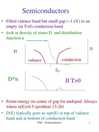
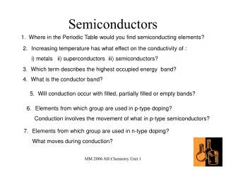
Introduction: Semiconductors are materials whose electrical properties lie between Conductors and Insulators. Ex : Silicon andGermanium
What are N-type and P-type ? • Semiconductors are classified in to N-type and P-type semiconductor • N-type: A N-type material is one in which electrons are majority charge carriers • i.e. they are negatively charged materials (-----) • P-type: A P-type material is one in which holes are majority carriers i.e. they are • positively charged materials (++++)
N-Type Material When extra valence electrons are introduced into a material such as silicon an n-type material is produced.The extra valence electrons are introduced by putting impurities or dopants into the silicon. The dopants used to create an n-type material are Group V elements. The most commonly used dopants from Group V are arsenic, antimony and phosphorus. The 2D diagram to the left shows the extra electron that will be present when a Group V dopant is introduced to a material such as silicon. This extra electron is very mobile. +4 +4 +4 +4 +5 +4 +4 +4 +4 2D diagram 5
P-Type Material P-type material is produced when the dopant that is introduced is from Group III. Group III elements have only 3 valence electrons and therefore there is an electron missing. This creates a hole (h+), or a positive charge that can move around in the material. Commonly used Group III dopants are aluminum, boron, and gallium. The 2D diagram to the left shows the hole that will be present when a Group III dopant is introduced to a material such as silicon. This hole is quite mobile in the same way the extra electron is mobile in a n-type material. + 4 +4 +4 +4 +3 +4 +4 +4 +4 2D diagram 6
Diodes Electronic devices created by bringing together a p-type and n-type region within the same semiconductor lattice It is represented by the following symbol, where the arrow indicates the direction of positive current flow.
Forward Bias Forward Bias : Connect positive of the Diode to positive of supply…negative of Diode to negative of supply fffffffffffffffffffffffffffffffffffffffffffffffffffffffffffffffffffffffffffffffffffffffffff
Reverse Bias Reverse Bias: Connect positive of the Diode to negative of supply…negative of diode to positive of supply. rrrrrrrrrrrrrrrrrrrrrrrrrrrrrrrrrrrrrrrrrrrrrrrrrrrrrrrrrrrrrrrrrrrrrrrrrrrrrrrrrrrrrrrrrrrrrr
Characteristics of Diode • Diode always conducts in one direction. • Diodes always conduct current when “Forward Biased” ( Zero resistance) • Diodes do not conduct when Reverse Biased (Infinite resistance)
Rectification • Converting ac to dc is accomplished by the process of rectification. • Two processes are used: • Half-wave rectification; • Full-wave rectification.
Half-wave Rectification • Simplest process used to convert ac to dc. • A diode is used to clip the input signal excursions of one polarity to zero.
Full-wave Rectification • Both diodes are conducting in any polarity
Shockley Equation • The transconductance curve on the previous slide is characterized by the following equation: Is is the saturation current ~10 -14 Vd is the diode voltage n – emission coefficient (varies from 1 - 2 ) k = 1.38 × 10⁻²³ J/K is Boltzmann’s constant q = 1.60 × 10⁻¹⁹ C is the electrical charge of an electron. At a temperature of 300 K, we have