AIM-1
AIM-1. SCIENCE GOAL Resolve Energetics, Sources and Couplings of Atmosphere-Plasma ESCAPE. Bill Lotko and Jim Clemmons . The Aerospace Corporation 8 March 2011. AIM-1 (Atmosphere-Plasma Outflows). Science Objectives. Mission. Key Challenges.

AIM-1
E N D
Presentation Transcript
AIM-1 SCIENCE GOAL ResolveEnergetics, Sources and Couplings of Atmosphere-Plasma ESCAPE Bill Lotko and Jim Clemmons The Aerospace Corporation 8 March 2011
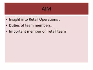
AIM-1 (Atmosphere-Plasma Outflows) Science Objectives Mission Key Challenges Key Instrument Parameters 117 kg, 96 W, 510 kbps Determine how ionospheric outflows are energized, the processes controlling their fluxes and distributions, and how they affect the AIM system Plasma and energy sources Coupling between thermosphere and ionospheric upflow, outflow Conversion of EM energy to charged-particle energy Altitude distribution of ion energization, outflow Observations/measurements • Electromagnetic and particle drivers • Thermal (3D), superthermal (2D) electron/ion phase-space densities • Local neutral gas density, composition, velocity (3D) • Auroral context from FUV images, plasma density sounding Field Instruments • Vector electric, magnetic fields: dc to 8 MHz (fpe) • Langmuir probe – local electron density and temperature • Plasma density sounder – ionospheric density profiles Thermal Electron/Ion Spectrometers • Quasi-3D electron and ion velocity distributions – 0.1 to 20 eV Superthermal Electron/Ion Spectrometer • Energy-pitch angle distributions (e-, H+, He+, O+)– 5 eV to 30 keV Wind Sensor – 3D neutral gas velocity Mass Spectrometer – neutral gas composition Ionization Gauge – neutral gas density FUV imager – 1356, LBH-S,L emissions Optimize orbits and s/c phasing for magnetic conjunctions in outflow regions • In cusp region, near nightside convection throat, auroral regions Connect low-altitude source regions with outflows observed near apogee • Ion dispersion mixes convective and field-aligned motions • O+ transit time between s/c (> 1 minute) Differentiate ion energization processes • Stochastic, resonant, convective pick-up energization processes • Influence of neutral gas properties on outflow fluxes • Scale couplings: Meso/micro cavitation, upwelling, energization 2 identical s/c, 3-axis stabilized Launch mass: XXXX kg per s/c Launch date: Near solar maximum 2 Taurus 3110 launches 84 inclination, coplanar orbits • Maintain common line of apsides • Apogees 180 out of phase • Topside, bottomside phases 500 km 2500 km (1 yr) 200 km 2500 km (1 yr) 275 km 2500 km (25-yr decay) 2
Top Risks and Challenges • Dual-satellite mission • Early failure of one s/c or instrumentation would diminish scientific return • New types of single-point measurements would continue to provide novel scientific results, but lack of magnetically conjugate measurements would impede the goal of understanding connections between outflows observed at higher altitude and their generation in the ionosphere and coupling to thermospheric processes • Dual-phase mission • Resolving both bottomside and topside processes contributing to outflow requires 2 mission phases: Diminished scientific return if one s/c or instrumentation fails prior to 2nd phase • Topside (phase 1) measurements in the energization region are a higher priority in understanding outflow processes • Possible interference issues between soundings and other measurements • Radiation exposure may limit instrument performance during an extended mission
Unique Investments and Technologies • First topside sounder since ISIS-2 (1971) Measurements of the ionosphericplasma den-sity profile, combined with SOA measurements of EM fields, charged particles, neutral gas and auroral emissions, provideunique opportunities to determine how ionospheric structure controls and is influenced by ionospheric outflows. • Two-point in-situ measurements along a single magnetic flux tube • FUV images with 7 km auroral resolution,10 sec/frame, 900 km FOV • Leverages Heliophysics System Observatory with in-situ measurements and images in a critical region of geospace • No new technologies are required, but the science would benefit from instrument developments in measuring low-density neutral gas properties near mission apogee (e.g., neutral polar wind)
Operational Strategy • Minimal delay between launches and commissioning of 2 s/c • Nominal 2 year mission in 2 phases • Topside: 500 km x 2500 km (1 year) • Bottomside: 200 km x 2500 km (1 year) • EOL orbit at 275 km x 2500 km would allow a useful extended mission and critical observations for the Heliophysics System Observatory • Orbit maintenance • Maintain coplanarity of orbits and common line of apsides • Orbital phase to maximize measurements in primary outflow regions (cusp, auroral) during magnetic conjunctions • Burst-mode data acquisition would be desirable for campaigns, e.g. coordination with ground-based instruments and intervals of active management of magnetic conjunctions • Choice of perigee may depend on solar-cycle phase at launch
Spacecraft Heritage and Analogies • Placeholder • Placeholder
Schedule Matrix • Placeholder • Placeholder
Cost Box – Summary Chart • Placeholder • Placeholder