
A Minimal Adaptive Routing Circuit Switched Architecture for Scalable and Parametric NoCs
This paper presents a novel architecture for Network-on-Chip (NoC) designs, focusing on minimal adaptive routing. The proposed MACS (Minimal Adaptive Circuit Switched) architecture improves data transfer efficiency between hardware modules by establishing communication channels along the shortest paths while dynamically adapting to network conditions. It utilizes a mesh topology with switches containing multiple ports and lanes, optimizing routing and resource allocation. The architecture aims to reduce latency, avoid bottlenecks, and provide alternate communication paths, resulting in more efficient NoC performance.

A Minimal Adaptive Routing Circuit Switched Architecture for Scalable and Parametric NoCs
E N D
Presentation Transcript
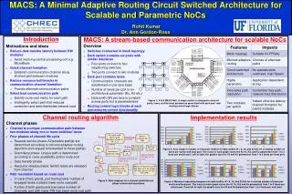
MACS: A Minimal Adaptive Routing Circuit Switched Architecture for Scalable and Parametric NoCs Rohit KumarDr. Ann Gordon-Ross up_data_out up_dny_out up_data_in up_req_out up_gnt_out up_ful_out up_dny_in up_req_in up_gnt_in up_ful_in l_loc_gnt_in l_loc_dny_in l_loc_req_in kd*w kd ku ku ku kd kd kd ku ku*w l_loc_ful_in Up Switch Port Left Switch Port Right Switch Port ExSIF InSIF kr*w kl*w right_data_in left_data_in kr kl right_req_in left_req_in kl kr S S left_gnt_in right_gnt_in Routing Control Logic Blocks S ExSIF ExSIF kl kr right_dny_in left_dny_in kl kr l_loc_gnt_out l_loc_req_out l_loc_dny_out l_loc_ful_out right_ful_in left_ful_in N N N N N N N N N N N N kr kl right_ful_out left_ful_out kr kl Routing Control Logic right_dny_out left_dny_out kr kl left_gnt_out right_gnt_out InSIF InSIF kl kr right_req_out left_req_out kl*w kr*w left_data_out right_data_out Routing Control Logic Blocks S S S Left Local Port Right Local Port ExSIF ExSIF Krl*w Kll*w Krl Kll N N N Krl Kll Krl Kll Krl r_loc_req_in l_loc_data_in Kll r_loc_data_in Krl InSIF Kll InSIF Introduction r_loc_gnt_in Krl MACS: A stream-based communication architecture for scalable NoCs Kll r_loc_dny_in Krl Kll Krl r_loc_ful_in Kll r_loc_ful_out Krl*w ExSIF InSIF Kll*w r_loc_dny_out S S S r_loc_gnt_out r_loc_req_out r_loc_data_out ku*w ku kd kd kd ku ku ku kd kd*w l_loc_data_out N N N Try route in all shortest path directions (at most 2: ‘C0’, ‘C1’) Reserve resources for OKs Request One or both available Overview • Switches connected in mesh topology • Each switch contains six ports with similar interfaces • Four ports connect to four neighboring switches • Two ports connect to two modules • Each port contains lanes • Communication channels are established on per lane basis • Number of lanes per port is an architectural parameter (Ku, Kd etc.) • Data width (W) per lane is constant across ports but is parameterized • Routing control logic blocks at each port ensures correct functionality Motivations and ideas • Reduce data transfer latency between HW modules • Avoid involving central processing unit e.g. MicroBlaze • Quick channel formation • Establish communication channel along shortest path between modules • Reduce resource bottlenecks in communication channel formation • Provide alternate communication paths • Select best communication path • Identify route cost metric for each path • Intelligently select path that reduces contention and best distributes network load down_data_out down_dny_out down_gnt_out down_data_in down_req_out down_ful_out down_dny_in down_req_in Down Switch Port down_gnt_in No available route down_ful_in Idle Wait for all grants/denies Forward request All denies Send deny to requesting switch Release all All grants if both ‘C0’ and ‘C1’ are resent Release all Grant on ‘C0’, deny on other, if any No more data Send grant of ‘C0’ to requesting switch. Release resources for ‘C1’ if any Port in ‘C0’ has lower no. of busy lanes, or if no. of lanes are same, port in ‘C1’ has lower PID Data transfer Figure 1: A 3x3 MACS NoC. A single switch is enlarged to show all ports, lanes, architectural parameters associated with each port and routing control logic blocks Channel routing algorithm Implementation results Channel phases • Channel is a unique communication path between two modules along one or more switches' lanes • Four phases of channel life cycle • Request service phase: All possible path(s) are determined according to minimal adaptive routing algorithm and request is forwarded to those path(s) • Grant/deny phase: Unique path is determined according to route availability and/or route cost • Data transfer phase • Resource release phase: Switch lanes are released from channel • Path resolution based on route cost • In case of two grants, port having lower number of engaged lanes contains lower route cost path • Further, if both grant ports has same number of channels, port with lower PID has lower route cost path


