Download
1 / 31
310 likes | 465 Vues
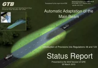
GTB Automotive Lighting and Light Signalling Expert Group (Groupe de Travail "Bruxelles 1952" (GTB)). Automatic Adaptation of the Main Beam. Introduction of Provisions into Regulations 48 and 123 Status Report. Presented to the 63rd Session of GRE 30 March 2010. GTB

E N D
GTB Automotive Lighting and Light Signalling Expert Group (Groupe de Travail "Bruxelles 1952" (GTB)) Automatic Adaptation of the Main Beam Introduction of Provisions into Regulations 48 and 123 Status Report Presented to the 63rd Session of GRE 30 March 2010
GTB Automotive Lighting and Light Signalling Expert Group (Groupe de Travail "Bruxelles 1952" (GTB)) GTB Presentation relating to item 5 (d) of the agenda for the 63rd GRE session Extract of ECE/TRANS/WP.29/GRE/2010/1 + Add. 1 5 (d) Regulations Nos. 48 and 123 ECE/TRANS/WP.29/GRE/62, paras. 14 and 22 (ECE/TRANS/WP.29/GRE/2009/56) (ECE/TRANS/WP.29/GRE/2009/57) (ECE/TRANS/WP.29/GRE/2009/59) (GRE‑62‑05) (GRE‑62‑13) (GRE‑62‑14) (GRE‑62‑16) (GRE‑62‑17) (GRE‑62‑18) (GRE‑62‑19) (GRE‑62‑20) (GRE‑62‑21) GRE may wish to resume discussion on this agenda item, including also automatic activation/deactivation of main beam, awaiting consolidated and revised proposals, if available. GRE may wish to consider on Tuesday, 30 March 2010 at 4.30 p.m. a presentation of the status of discussions of GTB with support of GRE experts and an overview of the approach to introduce provisions into the Regulations. In the meantime, it is also expected an overview of the experience of vehicle manufacturers (who have the responsibility for the complete system performance). On Wednesday, 31 March 2010 at 9.30 a.m., GRE is expecting to hold an open discussion and exchange of views with GRE experts to understand the concerns and requirements of the contracting parties concerning necessary provisions to be introduced into the Regulations. Finally, GRE may wish to consider the next steps based upon the GTB objective to submit official proposals for the October 2010 session of GRE.
Introduction GRE 60th session (Oct. 2008) Concept and demonstration of prototypes Informal document “Presentation by GTB - AFS main beam (driving beam) improvements”. GRE 62nd session Formal proposals to amend Regulations 48 and 123 with accompanying presentation (ECE/TRANS/WP.29/GRE/2009/56) / (ECE/TRANS/WP.29/GRE/2009/57) (ECE/TRANS/WP.29/GRE/2009/59) (GRE‑62‑05) (GRE‑62‑13) (GRE‑62‑14) (GRE‑62‑16) (GRE‑62‑17) (GRE‑62‑18) (GRE‑62‑19) (GRE‑62‑20) (GRE‑62‑21) GTB taskforce continued to work to develop proposals taking into account the comments received. It was agreed that it would be helpful for GRE experts to be informally invited to participate in the GTB taskforce meeting. GTB Taskforce meetings with participation of GRE Experts Paris 25 November 2009 / Frankfurt 26 January 2010 / Karlsruhe 25 February 2010
Agenda • Technology Update • Safety Issues • The Regulatory Challenge • Status report • Discussion related to open issues (09:30 on 31 March) • Formal Proposals for GRE 64th session (Oct 2010)
Technology Status Automatic activation / deactivation of the main beam Senses the presence of oncoming and preceding vehicles and automatically activates / deactivates the main beam Sensor (Taken from ISAL 2009 Paper A35)
Technology Status Adaptive Dipped Beam Cut- off Line Based upon a sensor system identifying the positions of other vehicles and connected to an image processor and electronic control unit (ECU) to automatically adapt the dipped beam cut-off to provide optimised glare controlled illumination of the road scene ahead Sensor (Taken from ISAL 2009 Paper A35)
Technology Status Adaptive Dipped Beam Cut- off Line Adaption sequence 1 6 1 4 2 5 3 6 (Taken from ISAL 2009 Paper A35)
Technology Status Adaptive Main Beam Main beam adapting to the presence of other vehicles to provide optimised glare controlled illumination of the road scene ahead Sensor (Taken from ISAL 2009 Paper A35)
Technology Status Adaptive Main Beam Adaption sequence 1 6 1 4 5 2 6 3 (Taken from ISAL 2009 Paper A35)
Technology Status Dipped Beam Adaptive Main Beam Improved visibility for detection of pedestrians, cyclists, lane guidance etc. Main Beam Adaptive Partial Main Beam (Taken from ISAL 2009 Paper A36)
Technology Status • First application of this technology on high range vehicles sold globally • Safety of prime concern • Introduced as part of an AFS lighting System • Manufacturer liability • Manufacturer‘s vehicle brand image and reputation at stake • Vehicle manufacturers investment in extensive development and proving • Technological support from equipment suppliers • Vehicle manufacturers will only launch this technology after gaining a high level of confidence
Technology Status Extensive experience with senor systems on vehicles. Objective performance specifications well established Image processing and generation of appropriate control systems is based upon algorithms developed by the vehicle manufacturer in conjunction with suppliers. These algorithms are the result of extensive testing in real-world conditions. Objective performance specifications difficult to prescribe. Lighting electronics, optical techniques and headlamp construction technology are all well developed based upon AFS experience. Objective performance specifications well established
Technology Status • Systems tested: • over a period of 2 years • under all real road conditions in Europe and USA • over more than 1 million Km
Safety Issues • Optimised use of main beam • Reduces driver fatigue through improved visibility and by reducing the work load BUT the driver remains responsible for deciding when it is appropriate to use the main beam and when to switch to dipped beam (Taken from ISAL 2009 Paper A36)
Safety Issues Enhanced detection of pedestrians • SAE Information Report J2829 produced in conjunction with GTB and CIE identifies minimum requirements for the detection of pedestrians and shows that in many cases the dipped beam is incapable of providing sufficient visibility. ISAL 2009 Paper A36 concludes (Taken from ISAL 2009 Paper A36)
Safety Issues • Enhanced detection of bicycles • Cycles equipped with good lighting will be detected by the system which will react and adapt the main beam to avoid causing discomfort. • In the case of cycles not having good lighting it is preferable for a driver to be able to recognise them through the use of the main beam even at the risk of causing some glare discomfort. • Many concerns relating to cyclist safety due to • poor or no lighting on the cycle, • No standard cycle lighting performance • high proportion of crashes not involving other vehicles • Conclusion: There is no strong case to compromise the potential benefits of improved detection of cyclists through the use of ADB systems. Most cyclist accidents and fatalities occur in urban areas where the ADB system is deactivated.
The Regulatory Challenge • How to introduce objective requirements • into the regulations? • Assure safety and avoidance of compliants from other road users • Technology Independent • Provisions that can be verified during type approval • Validatation of the effectiveness of the software
Definition of Adaptive Main Beam • “Adaptive main-beam" means a main-beam of the AFS that adapts its beam pattern to the presence of oncoming and preceding vehicles in order to improve long-range visibility for the driver without causing discomfort, distraction or glare to other road users.
Sensor Requirements • ……….the control signals being produced by a sensor system which is capable of detecting and reacting to all the following: • ambient lighting conditions; • the light emitted by the front lighting, front light-signalling devices or retro-reflected light of oncoming vehicles; • the light emitted by the rear light-signalling devices or retro-reflected light of preceding vehicles. • Additional sensor functions to improve performance are allowed. • Vehicles” means vehicles of categories L, M, N, O, T, and additionally includes bicycles] equipped with retro-reflectors and front lighting which is switched ON. Open Issue Are different sensor characteristics required for the automatic activation / deactivation and for the adaptive systems?
Sensor Requirements Minimum Detection Angles • The sensor used to control the adaptation of the main-beam shall comply with the following requirements: • The boundaries of the minimum fields in which the sensor is able to detect (light emitted or retro-reflected) from other vehicles are defined by the angles indicated below. These angles are measured from the centre of the sensor aperture relative to a horizontal straight line through its centre and parallel to the longitudinal median plane of the vehicle. • Horizontal angles: 15° to the left and 15° to the right. • Vertical angles: 5° upwards and 2° downwards ; • [depending upon the mounting height of the sensor] Open Issue
Sensor Requirements Minimum Detection Distance • The sensor shall be able to detect on a straight level [flat] road: • an oncoming power driven vehicle at a distance extending to at least 300 [450] m • a preceding power driven vehicle or a vehicle/ trailers combination at a distance extending to at least [100] 200 m; • an oncoming bicycle at a distance extending to at least 50 m with the illumination corresponding to a white lamp with a luminous intensity of 150 cd with a light emitting surface of at least 10 cm² and at a height above the ground of 0.8m. Open Issue
Sensor Requirements Minimum Detection Distance UMTRI Research “While regional differences in high-beam use were observed, substantial underuse of high-beam headlamps was present in all areas of the country. In car-meeting scenarios, on average, drivers dimmed their high beams at an inter-car distance of 522 m. From an obstacle detection standpoint, Helmers and Rumar **(1974) reported a distance of 250 m to 400 m as an optimal distance for switching from high to low beams. The dimming distances observed by Hare and Hemion were clearly substantially longer than is advisable for object detection and occurred at distances at which disability glare is not a factor.” ** Professor Kare Rumar of the Swedish Road and Traffic. Research Institute
Sensor Requirements Minimum Detection Distance Technical University - Darmstadt Research This is new research and further analysis is required.
Sensor Requirements Minimum Sensitivity • The challenge is to differentiate between oncoming vehicles and the road infrastructure, especially red and white retro reflecting devices • Setting a low detection range for bicycles may result disproportionately in an increased number of false main beam turn-offs. • Driver acceptance of ADB systems is based on correct performance: • minimization of false main beam turn-offs • reacting to clearly visible, self illuminated road users
Sensor Requirements Minimum Sensitivity 100cd cycle lamp at 32m distance French road edge marker at 75m distance Conclusion: Do not attempt to detect bicycle lamps having an intensity of less than 200cd
Photometric Requirements (R123) To verify correct reaction of the headlamp to control signals • In the case of adaptation of the main-beam function the system shall meet the requirements only in the maximum position of activation. • During adaptation, the main-beam function shall meet the requirements for all the cases of Right-Hand and Left-Hand traffic • Requirements shall be verified during the type approval testing in conjunction with a signal generator to be provided by the applicant. • If the requirements can be met either for the Right-Hand traffic or the Left-Hand traffic only, the relevant information shall be noticed in the communication document Open Issue
Performance Verification Open Issue Verification: that the adaptationof the main-beam does not cause any discomfort, distraction or glare, neither to the driver nor to oncoming and preceding vehicles, Technical service shall: perform a test drive in clear atmosphere at all relevant speed, which comprises any situation relevant to the system control on the basis of the applicants description; activation, performance and deactivation of adaptation of the main-beam shall be recorded and checked against the data submitted by the applicant. A matrix of specific aspects of the performance of the system to be evaluated during the test drive is proposed The overall performance of the automatic control shall be demonstrated by the applicant by documentation or by other means accepted by the authority responsible for type approval.
Next Steps • A summary of the approach developed by the GTB Taskforce identifying the open issues to be resolved is available as a GRE63 informal document • GTB would appreciate initial reactions and advice from GRE experts • Open Discussion Wednesday 31 March 2010 at 09:30 • Formal proposal by GTB for GRE64 (October 2010), taking into account the input from GRE experts.
Open Discussion Wednesday 31 March Agenda • Main open issues to be addressed: • Does the definition of a standard performance for bicycle lamps satisfy the requirements of the contracting parties to take the effects of the system upon cyclists into account? • Are different sensor characteristics required for the automatic activation / deactivation and for the adaptive systems? • Should the sensing requirements be 300/100 metres or 450/250m respectively? • What requirements should be defined for the verification of satisfactory performance during a test drive by the technical services? Should there be different requirements for automatic activation and deactivation and for adaptive systems? • Is it permissible for the system to be designed for right hand traffic or left hand traffic only?
Thank you for your attention GTB Automotive Lighting and Light Signalling Expert Group (Groupe de Travail "Bruxelles 1952" (GTB))