Download
1 / 29
300 likes | 491 Vues
This presentation will probably involve audience discussion, which will create action items. Use PowerPoint to keep track of these action items during your presentation In Slide Show, click on the right mouse button Select “Meeting Minder” Select the “Action Items” tab

E N D
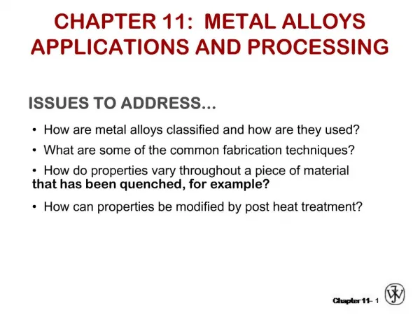
This presentation will probably involve audience discussion, which will create action items. Use PowerPoint to keep track of these action items during your presentation • In Slide Show, click on the right mouse button • Select “Meeting Minder” • Select the “Action Items” tab • Type in action items as they come up • Click OK to dismiss this box • This will automatically create an Action Item slide at the end of your presentation with your points entered. Fundamental Imaging Characteristics and Resolution of Metal Alloys By Marc G. Apple, M.D. Mark Michael
Fort Wayne Metals was founded and continues to grow because of our dedication to the medical device field “Our mission is to continuously improve the quality of our products, the speed and efficiency with which we respond to our customers requests, and the knowledge of the materials we work with and recommend.” FWM’s Mission Statement
Typical Wire Application Need • Diameter • Strength • Fatigue • Corrosion Resistance • Electrical Resistance • Formability But Now…
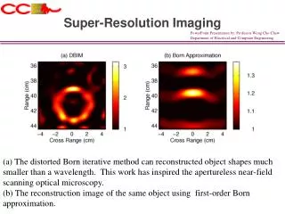
Imaging • What size wire should I use? • Which alloy will work best? • Will flat wire be better than round? • How can we find answers? • What modality will you use? • What is a good image? • What technology will be used?
Where did we start • Most implantable wires lose imaging capability under .004”(.1mm) • The best still perform around .001”(.025mm)
The Concept • Choose wire diameters from .001” to .011” (.025mm to .28mm) • Choose common alloys and candidate alloys • Mount in stable fashion • Characterize using common modalities
Wire Diameters 90 Pt 10 Ni
MP35N Commercially Pure Titanium Tantalum Nitinol Platinum-10 Ni DBS(7) MP-DFT® 28Ag Coni-DFT® 33Pt Candidate Alloys and Materials
Candidate Alloys and Materials • 304V • 316LVM • Gold • Platinum • L605 • Custom 455
Selecting Modalities • Dr. Marc Apple at Parkview Oncology Center • Discuss imaging from a clinician point of view • Choose common modalities: Ximatron Hi-Res FluoroscopyPicker PQS CT Scanning SimulatorSiemans Magnetic Resonance Imaging
Ximatron Hi-Res Fluoroscopy 100 cm source to surface distance 110kv; 25ma; 3mas, 1.5mag latitude for technician
Clinician Comments • Amazed at variation due to equipment set up • Observed “zebra stripe effect” in bird’s eye view
Picker “PQS” System “CT Scan” 130kv; 150ma; pitch=1.5 latitude for technician
CT Scan of Wire Frame Thanks to Katie Shively, R.T.T. Parkview Hospital Regional Cancer Center Fort Wayne, Indiana
Variables in Imaging • Media- Impact of bolus was significant • Default equipment settings
MRI Measurement Parameters • “Magnetom Harmony” Class • 1.0 Tesla magnetic field • Operated at a 42 M#2 frequency • Used head coil with IR=415.0 • 15 internal slices with 3-D reconst • 3.00mm slice thickness, 0 skip • 192 x 256 matrix • Contrast setting W=792-798, C=369-376 • All images obtained using T-1 weighting
Variables in Imaging • Head coil was necessary to obtain images • Resolution was better than presented images
Next Step Options • Explore impact of form on imaging (flat wire, strand, cable, shapes) • Explore surface condition impact (plating, oxides, textures) • Move on to other Modalities (Ultrasound)
Conclusions • Novel pilot study to preemptively evaluate tissue equivalent characteristics before prototype devices • This protocol may prove useful as reference data for diameter and material selection