Optimizing LLRF System for Low-Noise Field Detectors at XFEL
This workshop covers stability requirements, noise limitations, down-converter prototypes, and LLRF phase noise budget for the XFEL, focusing on noise reduction methods and improvements for detector operation. It also discusses measuring bandwidth and the next LLRF system with optimized detector operation. Technologies like jitter transformation and down-converter limitations are explored, with a focus on noise, linearity, and dynamic range. Filtering distortions and signal linearization techniques are detailed. The workshop concludes with a summary and outlook on enhancing the CW-modulation scheme for field detector applications.

Optimizing LLRF System for Low-Noise Field Detectors at XFEL
E N D
Presentation Transcript
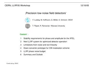
CERN, LLRF05 Workshop 12/10/05 ‚Precision low-noise field detectors‘ F. Ludwig, M. Hoffmann, G. Möller, S. Simrock / DESY T. Filipek, R. Romaniuk / Warsaw University Content : 1 Stability requirements for phase and amplitude for the XFEL 2 Next LLRF system for optimized detector operation 3 Limitations from noise and non-linearity 4 Down-converter prototype for CW-modulation scheme 5 LLRF phase noise budget 6 Summary and Outlook
Stability requirements on phase and amplitude for the XFEL • Actual LLRF control system using a switched LO-signal : Amplitude stability : - Rotation of the LO-signal in four 90o steps using a squared LO-Signal. Phase stability : • Bandwidth for transforming the • squared LO-signal : voltage 0.5V/div voltage 2mV/div • Stability requirements of the cavity field vector sum : voltage 0.5V/div time 500us/div time 100ns/div peak-to-peak comparison (normalized to A=1V) time 5us/div ACC5, Probe DCW, AN-36 - 86dB dynamic range of signal-to-noise.
Next LLRF system for optimized detector operation Where comes the noise from and what do we measure after the down-converter ? Microphonics . . . We measure all noise sources of the loop for a finite gain, but not the residual jitter between beam and reference! How can we improve this ? • - Conceptional improvements using noise reduction methods, e.g. filtering and averaging. • Sort the priorities: low noise, low drift, high linearity, absolute accuracy. • Improve each component. • - Minimize residual jitter by increasing or decreasing the loop gain.
Next LLRF system for optimized detector operation Measuring bandwidth : • Proposed LLRF control system operating with a CW LO-signal : Master-Oscillator high-power cavity klystron 1300-81 Jitter transformation : RF-input 1300 down-converter LO-input 1300-81 81=9 x 9 FPGA DAC-clock ADC-clock + Higher harmonics and disturbancies using bandpass filters can be suppressed. + Narrowband filtering the IF-signal reduces distortions from mixer non-linearities. + Averaging reduces ADC-noise and no aliasing effects. + No noise from LO-driver. - Precise synchronization system.
Down-converter limitations from noise and non-linearity • Compromise between noise and linearity : • Active Gilbert-mixers: • Passive Mixer + FET: + High conversion gain + Low LO drive needed + Low LO/RF crosstalk - Normal NF - Additional 1/f-noise • + High linearity • + Low NF • Large LO drive needed • (additional phase noise) • - High LO/RF crosstalk IP3 IP2 Non-linearity Noise floor Dynamic Range (DRout) Spurious Free Dynamic Range (SFDRout) Noise • Filtering of distortions : Filter Signal distortions : - intermodulation effects (IP3) - higher harmonics (IP2) Signalinformation Multi-channel detector board : - Filtering of distortions - Linearization during beam pauses - Gilbert cell mixer
Actual down-converter • Noise from actual down-converter : LLRF05: G.Möller, [43] Multichannel down-converter board for cavity field detection at the TTF. First mixer stage determines the noise performance. Actual down-converter performance: - - (Switched LO-Signal) (CW-LO-Signal) (Cavity filtered)
Down-converter prototype for CW-modulation scheme ADC clock 80 MHz 80 MHz Oversampling 1291 MHz Stripline Filter BPF LO-input -5dBm 1300-9 MHz 9MHz SMD-Filter Evaluation Board Active Mixer LT5522 Low-Noise-Amplifier LO Input Matching Circuit 1300 MHz Stripline Filter Attenuator AD6645 14 Bit, 80 MSPS, 100fs jitter BPF Output Matching Circuit Input Matching Circuit BPF IF Output Matching Circuit RF-input LNA 14 1300 MHz
Down-converter prototype for CW-modulation scheme • Undersampling : • Oversampling : Signal bandwidth: Bandlimited noise from Mixer Noise from ADC 0 5 10 15 20 25 30 35 40 0 5 10 15 20 25 30 35 40 ADC-noise, oversampling, clock phase noise requirements Oversampling promises better SNR than undersampling. LLRF05: T.Filipek, Frequency Conversion in Field Stabilization System for Application in SC cavity of linear accelerator.
LLRF phase noise budget – Residual jitter Beam jitter (simplified) 1st order LP 1st order HP 1st order LP - MO and klystron contributions decreases with gain. The effective noise bandwidth for the down-converter is given by : - Down-converter contributions increases with gain.
Phase noise budget (Switched LO, single cavity) • Phase noise spectra : • Contributions to residual jitter : - Noise is filtered by the cavity. TTF2 (new supply) Measured down-converter noise is larger than residual noise and beam jitter. • The down-converter is not a good • indicator for the residual jitter!
Phase noise budget (Switched LO, single cavity) • Phase noise spectra : • Contributions to residual jitter : - Noise is filtered by the cavity. TTF2 (new supply) Measured down-converter noise is larger than residual noise and beam jitter. • The down-converter is not a good • indicator for the residual jitter!
Summary and Outlook • Summary : • The CW-modulation scheme combines many advantages, for example : • - No aliasing effects and ADC-noise reduction. • - Filtering of distortions, which allows a linearization with improved SNR. • For multi-channel systems Gilbert mixers are recommended. • Oversampling promises better SNR than undersampling. • The down-converters noise contribution to the beam jitter • is reduced by the cavity transfer function. - Design a multi-channel board and test within accelerator environment. - Beam jitter caused by LLRF should be measured with fs-resolution. • Outlook : • Decrease mixers noise : • Increase mixer output : • Linearize the down-converters • characteristic within the beam pause. • - Passive front end structures. • Parallel structures of detectors (VLSI prefered). • pHEMT Gilbert mixers (promise higher gain and lower noise). • Additional „Zero-Phase“ detectors.
Summary and Outlook Thanks for your attention!
Summary and Outlook Backup Slides
Actual down-converter (Designed by G.Möller/DESY/MHF-p) + High LO/RF isolation - Mixing into baseband causes additional noise 8-channels to ADC-Board : 8-channels from cavity probe : LO-Input : LLRF05: G.Möller, [43] Multichannel down-converter board for cavity field detection at the TTF.
Choice of LLRF system for optimized detector operation • Actual LLRF control system using a switched LO-signal : • Phase and amplitude detection of the cavity field vector : Rotation of the LO-signal in four 90o steps, using a 250kHz squared LO-Signal. (-I,+Q) (+I,+Q) (-I,-Q) (+I,-Q) • Down-converter output IF-signal : voltage 0.5V/div voltage 0.5V/div Bandwidth for transforming 250kHz squared pulses : but required regulation bandwidth is only : time 500us/div time 5us/div
Down-converter prototype for CW-modulation scheme • SNR gain from ADC oversampling : I samples Digital I,Q-Detection Averaging or Filtering BPF BPF RF-input LNA ADC Q samples LO-input ADC clock x N : M SNR gain from averaging within the measuring time : Master-Oscillator Sample frequency Measuring bandwidth Clockjitter Internal jitter Equiv. Input noise of ADC Quant. noise • Number of samples : Oversampling - The signal within the bandbass filter, respectively noise from mixer stage will not be averaged. Undersampling Optimal IF frequency, clock phase noise requirements LLRF05: T.Filipek, Frequency Conversion in Field Stabilization System for Application in SC cavity of linear accelerator. Measuring bandwidth
IP3 IP2 Non-linearity Noise floor Spurious Free Dynamic Range (SFDRout) Noise Filter Signalinformation Down-converter limitations from noise and non-linearity • Compromise between noise and linearity : • Active Gilbert-mixers: • Passive Mixer + FET: + High conversion gain + Low LO drive needed + Low LO/RF crosstalk - Normal NF - Additional 1/f-noise • + High linearity • + Low NF • Large LO drive needed • (additional phase noise) • - High LO/RF crosstalk Dynamic Range (DRout) • Filtering of distortions : Signal distortions : - intermodulation effects (IP3) - higher harmonics (IP2) Multi-channel detector board : - Filtering of distortions - Linearization during beam pauses - Gilbert cell mixer