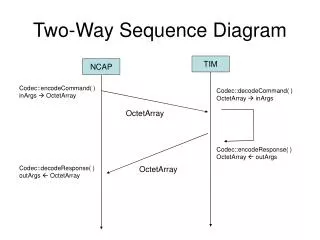
System sequence diagram
Asper School of Business University of Manitoba. Systems Analysis & Design. Instructor: Bob Travica. System sequence diagram. Updated: October 2013. Outline. Concept of SSD Global SSD Creating global SSD Detailed SSD (reading) First cut Full. Concept of System Sequence Diagram (SSD).

System sequence diagram
E N D
Presentation Transcript
Asper School of Business University of Manitoba Systems Analysis & Design Instructor: Bob Travica System sequence diagram Updated: October 2013
Outline • Concept of SSD • Global SSD • Creating global SSD • Detailed SSD (reading) • First cut • Full 3510 Systems Analysis & Design * Bob Travica
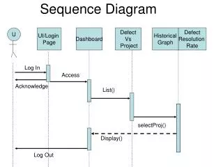
Concept of System Sequence Diagram (SSD) • Part of system design. Communicates to OO programmers. • SSD shows interaction between actors and system (global SSD), and among objects (detailed SSD) • SSD specifies flow of data (messages) • Messages are actions (resemble commands) invoked on destination object 3510 Systems Analysis & Design * Bob Travica
Global SSD Figure 6-14 Content of Item: SSD of a customer order system 3510 Systems Analysis & Design * Bob Travica
Global SSD – loops Figure 6-15 Note: extendedPrice = price * quantity Expected output True/False Condition Loop Input 3510 Systems Analysis & Design * Bob Travica
Creating global SSD 1. Start with an activity diagram and/or use case description. 2. Identify the input messages from actor to system. For figuring attributes (input parameters), use class diagram. 3. Identify/apply special conditions (iteration) to input messages, if any. 4. Identify output messages. 3510 Systems Analysis & Design * Bob Travica
Creating global SSD (cont.) Account accountNo customerID OrderDetail quantity extendedPrice places Order orderID accountNo TotalAmt contains Product productID size description CatalogProduct price Catalog catalogID Figure 6-16. Activity diagram of Create New Order use case, Telephone Scenario at RMO Figure 6-17. Global SSD of the same Figure 5-31 (detail). Class diagram of RMO
Detailed SSD • Uses the same elements as an SSD • Has extra elements: • The :System object is replaced by objects and messages within computer system • Objects are differentiated (e.g., control handler, domain, user interface) • Object activation period indicated 3510 Systems Analysis & Design * Bob Travica
Control handler object Activation lifeline Detailed SSD for Look Up Item Availability - first cut (actor and domain classes) Domain objects (replace :System) Figure 8-14 SSD for Look Up Item Availability use case 3510 Systems Analysis & Design * Bob Travica
Reading detailed SSD (first cut) • The system object is broken down to specific objects. • Inputs & outputs among objects are specified. Class diagram essential (follow associations). 3510 Systems Analysis & Design * Bob Travica
Additional objects Adding user interface and database to SSD • Add user interface and database objects to domain objects. Example function: Create new student. Figure 8-1 3. Store database object (record) 6. Store update 5. Update Student object 4. Update Student record 3510 Systems Analysis & Design * Bob Travica
Detailed SSD (final) - reading Database (DA=Data Access Layer) User Interface Figure 8-17: Final SSD for the use case Look Up Item Availability (product description, price, quantity in inventory) Reading: Specific catalog and inventory objects are initialized by user’s input, and it will get data from the corresponding database objects. 3510 Systems Analysis & Design * Bob Travica