PowerIT Sensor Technology: Performance and Safety in MV Switchgears
Explore why ABB chose Rogowski coils and voltage dividers for optimal performance and cost-effective solutions in MV switchgears. Learn about the benefits of PowerIT Sensor Technology.

PowerIT Sensor Technology: Performance and Safety in MV Switchgears
E N D
Presentation Transcript
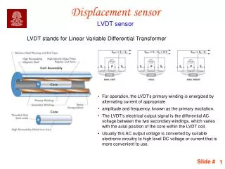
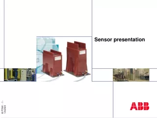
Product Scope • A Sensor is a device intended to transmit a signal corresponding to the primary current or voltage to the secondary equipment. • PowerIT Sensors are typically used in MV switchgears and switches for measuring, protection and indication.
Sensors vs. Instrument Transformers . . . but not in transformers! Trends in electrical engineering Size Performance Standardisation
Sensors vs. Instrument Transformers Reason: The properties of material used Saturation Unlinear range Linear range Unlinear range Remedy: Absence of iron
Why did ABB choose Rogowski coil • IEC-requirements • Cost effective • Low life cycle cost • Size Rogowski coil
Rogowski coil • First published in1912 by Rogowski and Steinhous • Uniformly wound coil with non-magnetic core • Output signal is proportional to the derivate of primary current • IEC 60044-8
Why did ABB choose voltage dividers • IEC-requirements • Cost effective • Safe • Low life cycle cost • Size Capacitive voltage divider Resistive voltage divider
Voltage divider Resistive divider • Matched resistor pair • 1:10 000 divider ratio • Today accuracy up to class 1 Capacitive divider • Zc = 1/C • 1:10 000 divider ratio • Accuracy up to class 3 • Small size ideal for bushings IEC 60044-7
Sensors vs. Instrument Transformers Rated primary current (CT) Ip (log) Ipr = 240 A
Sensors vs. Instrument Transformers Rated primary current range (sensor) Ip (log) Ipr = 80 A....240 A.........…1250 A
Sensors vs. Instrument Transformers Accuracy limit factor (Kalf) c Protection class 10P CS Ip (log) CT Ipr
Sensors vs. Instrument Transformers Linearity Typical error, voltage sensor
Sensors vs. Instrument Transformers Transmitted signal level Voltage transformer (ku=1,9) Voltage sensor 1,2 - 110 V, 25 VA At free potential, must be earthed Secondary losses =I2R 12 - 1100 mV, 80 mVA Always earthed in the sensor Secondary losses negligible Current transformer (Kalf =20) Current sensor 0,25 - 100 A, 5 VA At free potential, must be earthed Secondary losses = I2R 7,5 - 3000 mV, 6 mVA At free potential Secondary losses negligible High power Low power Low signal SAFE
Sensors vs. Instrument Transformers Short-circuited secondary Voltage transformer Voltage sensor 250 M Isc Isc 25 k Isc/Acu = 160 A/mm2 Temp.500 C Explosion within 30 s Isc = Inormal
Sensors vs. Instrument Transformers Open secondary Current transformer Current sensor Uopen Isc 0 - 10 kV Isc/Acu = 40 mA/mm2
Sensors vs. Instrument Transformers Frequency response rel CT F/Hz 10 100 1000 10 000 VS (Cap.) VS (Res.) VT CS
Sensors vs. Instrument Transformers Secondary wiring Terminal blocks Instr. transf. IED Wiring and screw connections Testing of connections Sensor IED Integrated cable and connector
Secondary cabling of sensors Sensor IED S1 S2
Sensors vs. Instrument Transformers Compactness Current transformer Combi Sensor Voltage transformer Small size of active parts Only one core
Sensor Technology - CT/VT vs. Sensors CT / VT Sensors Signal 1/5A / 100/110 V 150mV / 2V Secondary cables Excluded Incl. and tested Linearity No Yes Saturation Yes No Ferroresonance Yes (VT) No Temperature coefficient No Incl. in accuracy EMC No Shielded Short-circuited secondary Destructive (VT) Safe Open secondary Destructive (CT) Safe Weight 40-60 kg (CT + VT) 2-25 kg (Combi) Standardisation possible No Yes
Standards for Sensors Sensors from ABB are designed, manufactured and tested according to international standards when applicable. Voltage Sensors: IEC 60044-7 (1999-12) Instrument transformers – Part 7: Electronic voltage transformers Current Sensors: IEC 60044-8 (2002-07) Instrument transformers – Part 8: Electronic current transformers Combi Sensors: IEC 60044-3 (1980-01) Instrument transformers – Part 3: Combined transformers
Sensor, type KEVCD_ • Current sensor or Combi Sensor • Measurement and protection by one sensor • Dimensions and primary connections same as DIN-type CTs (DIN 42600) • 12, 17.5, 24 kV, two types: • A. </= 1250 A • B. > 1250 A (max. 3200 A) • Including coupling electrode for voltage indication
Selection Guide for KEVCD type Sensors Nominal voltage Rated current range (first row) Functions included (second row) < 1250 A 1600...3200 A I + U + Uind I + Uind I + U + Uind I + Uind Upto 12 kV KEVCD 12 AE3 KEVCD 12 AG3 KEVCD 12 BE2 KEVCD 12 BG2 Upto 17.5 kV KEVCD 17.5 AE3 KEVCD 17.5 AG3 KEVCD 17.5 BE2 KEVCD 17.5 BG2 Upto 24 kV KEVCD 24 AE3 KEVCD 24 AG3 KEVCD 24 BE2 KEVCD 24 BG2
Technical Information in KEVCD Sensor KEVCD 12 AE3 I-sensor Ipn: 1250 A • Ipr (to be advised), options: 80 A (Ir of switchgear: 80-160 A) • 240 A (Ir of switchgear: 160-480 A), with adapter • 640 A (Ir of switchgear: 480-1250 A), with adapter Output signal: 150 mV (50 Hz), 180 mV (60 Hz) Accuracy: Class 1* / 3 (*with correction factor) U-sensor Division ratio: 10.000/1 Accuracy: Class 1/3P Ith / Idyn: 40 kA, 3s / 100 kA Insulation level: 12/28/75 kV Frequency: 50/60 Hz With ribs on top Secondary cable (length to be advised), options: 5 m, 6.5 m or 7.5 m Primary polarity (to be advised), options: Normal or reversed Coupling electrode for voltage indication included
Sensors in use around the world In use in 56 countries More than 20 000 sensors in operation
Arguments for Sensors Safety Short delivery time Smart integration