Chapter 4: Network Layer Part A
Course on Computer Communication and Networks , CTH/GU The slides are adaptation of the slides made available by the authors of the course’s main textbook. Chapter 4: Network Layer Part A. Consider transporting a segment from sender to receiver

Chapter 4: Network Layer Part A
E N D
Presentation Transcript
Course on Computer Communication and Networks, CTH/GU The slidesare adaptation of the slidesmadeavailable by the authorsof the course’smaintextbook Chapter 4: Network LayerPart A 3: Transport Layer
Consider transporting a segment from sender to receiver sending side: encapsulates segments into datagrams receiving side: delivers segments to transport layer network layer protocols in everyhost, router router examines header fields in all datagrams passing through it network data link physical network data link physical network data link physical network data link physical network data link physical network data link physical network data link physical network data link physical network data link physical network data link physical network data link physical application transport network data link physical application transport network data link physical Network layer Network Layer
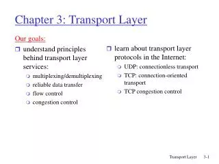
Roadmap understand principles ofnetwork layer services: • forwarding versus routing • network layer service models • how a router works • The Internet Network layer: IP, Addressing & related • routing • path selection) • instantiation, implementation in the Internet Today Next Network Layer
routing algorithm local forwarding table header value output link routing algorithm determines path through network forwarding table determines local forwarding at this router 0100 0101 0111 1001 3 2 2 1 value in arriving packet’s header 1 0111 2 3 Interplay between routing and forwarding Network Layer
example services for individual datagrams: guaranteed delivery guaranteed delivery with less than 40 msec delay example services for a flow of packets: in-order delivery guaranteed minimum bandwidth to flow restrictions on changes in inter-packet time-spacing Network service model Q: What service model for “channel”carrying packetsfrom sender to receiver? Network Layer
Connection, connection-less service • datagram network provides network-layer connectionlessservice (Internet model) • virtual-circuit network provides network-layer connectionservice (not in Internet) • analogous to TCP/UDP connection-oriented / connectionless transport-layer services, but: • service:host-to-host • no choice:network provides one or the other • implementation:in network core Network Layer
“source-to-dest path behaves almost like telephone circuit” call setup, teardown for each call before data can flow signaling protocols to setup, maintain, teardown VC (ATM, frame-relay, X.25; not in IP) each packet carries VC identifier (not destination host) everyrouter maintains “state” for each passing connection resources (bandwidth, buffers) may be allocated to VC (dedicated resources = predictable service) application transport network data link physical application transport network data link physical Virtual circuits: 6. Receive data 5. Data flow begins 4. Call connected 3. Accept call 1. Initiate call 2. incoming call 4: Network Layer
VC forwarding table 22 32 12 3 1 2 VC number interface number forwarding table in northwest router: Incoming interface Incoming VC # Outgoing interface Outgoing VC # 1 12 3 22 2 63 1 18 3 7 2 17 1 97 3 87 … … … … VC routers maintain connection state information! Network Layer
no call setup at network layer routers: no state about end-to-end connections no network-level concept of “connection” packets forwarded using destination host address application transport network data link physical application transport network data link physical Datagram networks (the Internet model) 1. send datagrams 2. receive datagrams Network Layer
4 billion IP addresses, so rather than list individual destination address list range of addresses (aggregate table entries) 1 3 2 Internet Datagram forwarding table routing algorithm local forwarding table dest address output link address-range 1 address-range 2 address-range 3 address-range 4 3 2 2 1 IP destination address in arriving packet’s header Network Layer
Datagram forwarding table Destination Address Range 11001000 00010111 00010000 00000000 through 11001000 00010111 00010111 11111111 11001000 00010111 00011000 00000000 through 11001000 00010111 00011000 11111111 11001000 00010111 00011001 00000000 through 11001000 00010111 00011111 11111111 otherwise Link Interface 0 1 2 3 Q: but what happens if ranges don’t divide up nicely? Network Layer
Longest prefix matching longest prefix matching when looking for forwarding table entry for given destination address, use longest address prefix that matches destination address (more on this coming soon) Link interface 0 1 2 3 Destination Address Range 11001000 00010111 00010*** ********* 11001000 00010111 00011000 ********* 11001000 00010111 00011*** ********* otherwise examples: which interface? DA: 11001000 00010111 00010110 10100001 which interface? DA: 11001000 00010111 00011000 10101010 Network Layer
Internet (datagram) data exchange among computers “elastic” service, no strict timing req. many link types different characteristics uniform service difficult “smart” end systems (computers) can adapt, perform control, error recovery simple inside network, complexity at “edge” VC (eg ATM: a past’s vision of the future’s ww-network) evolved from telephony human conversation: strict timing, reliability requirements need for guaranteed service “dumb” end systems telephones complexity inside network Datagram or VC network: why? Network Layer
Roadmap understand principles ofnetwork layer services: • forwarding versus routing • network layer service models • how a router works • The Internet Network layer: IP, Addressing & related • routing • path selection) • instantiation, implementation in the Internet Today Next Network Layer
high-seed switching fabric Router architecture overview two key router functions: • runrouting algorithms/protocol (eg: RIP, OSPF, BGP; more on these next lecture) • forwardingdatagrams from incoming to outgoing link forwarding tables computed, pushed to input ports routing processor routing, management control plane (software) forwarding data plane (hardware) router input ports router output ports Network Layer
Input port functions lookup, forwarding queueing switching: • given datagram dest., lookup output port using forwarding table in input port memory (“match plus action”) • goal: complete input port processing at ‘line speed’ • queuing: if datagrams arrive faster than forwarding rate into switch fabric link layer protocol (receive) switch fabric line termination physical layer: bit-level reception data link layer: e.g., Ethernet see chapter 5 Network Layer
Switching fabrics • transfer packet from input buffer to appropriate output buffer • switching rate: rate at which packets can be transfer from inputs to outputs • often measured as multiple of input/output line rate • N inputs: switching rate N times line rate desirable • three types of switching fabrics: memory bus memory crossbar Network Layer
output port (e.g., Ethernet) input port (e.g., Ethernet) memory system bus Switching via memory first generation routers: • traditional computers with switching under direct control of CPU • packet copied to system’s memory • speed limited by memory bandwidth (2 bus crossings per datagram) Network Layer
Switching via a bus • datagram from input port memory to output port memory via a shared bus • bus contention: switching speed limited by bus bandwidth • 32 Gbps bus, Cisco 5600: sufficient speed for access and enterprise routers bus Network Layer
crossbar Switching Via An Interconnection Network • Overcome bus bandwidth limitations • Banyan networks, other interconnection nets (also used in processors-memory interconnects in multiprocessors) • Advanced design: fragmenting datagram into fixed length cells, switch cells through the fabric (ATM-network principle). • Cisco 12000: switches at 60 Gbps 4: Network Layer
datagram buffer queueing Output ports • buffering required when datagrams arrive from fabric faster than the transmission rate • queueing (delay) and loss due to output port buffer overflow! • scheduling discipline chooses among queued datagrams for transmission (more on packet scheduling later) switch fabric line termination link layer protocol (send) Network Layer
Roadmap understand principles ofnetwork layer services: • forwarding versus routing • network layer service models • how a router works • The Internet Network layer: IP, Addressing & related • routing • path selection) • instantiation, implementation in the Internet Today Next Network Layer
host, router network layer functions: • IP protocol • addressing conventions • datagram format • packet handling conventions forwarding table The Internet network layer transport layer: TCP, UDP • routing protocols • path selection • RIP, OSPF, BGP network layer • ICMP protocol • error reporting • router “signaling” link layer physical layer Network Layer
IP protocol version number 32 bits total datagram length (bytes) header length (bytes) type of service head.len ver length for fragmentation/ reassembly “type” of data (prio) fragment offset flgs 16-bit identifier max number remaining hops (decremented at each router) upper layer time to live header checksum 32 bit source IP address 32 bit destination IP address upper layer protocol to deliver payload to e.g. timestamp, record route taken, specify list of routers to visit. options (if any) data (variable length, typically a TCP or UDP segment) IPv4 datagram format how much overhead? • 20 bytes of TCP • 20 bytes of IP • = 40 bytes + app layer overhead Network Layer
IP address: 32-bit identifier for host, router interface interface: connection between host/router and physical link router’s typically have multiple interfaces host typically has one or two interfaces (e.g., wired Ethernet and wireless 802.11) IP addresses associated with each interface 223.1.1.2 223.1.3.27 IP addressing: introduction 223.1.1.1 223.1.2.1 223.1.1.4 223.1.2.9 223.1.1.3 223.1.2.2 223.1.3.2 223.1.3.1 223.1.1.1 = 11011111 00000001 00000001 00000001 223 1 1 1 Network Layer
IP address: subnet part - high order bits (variable number) host part - low order bits what’s a subnet ? device interfaces with same subnet part of IP address can physically reach each other without intervening router subnet Subnets 223.1.1.1 223.1.2.1 223.1.1.2 223.1.1.4 223.1.2.9 223.1.1.3 223.1.2.2 223.1.3.27 223.1.3.2 223.1.3.1 network consisting of 3 subnets Network Layer
recipe to determine the subnets, detach each interface from its host or router, creating islands of isolated networks each isolated network is called a subnet 223.1.1.0/24 223.1.2.0/24 223.1.1.1 223.1.2.1 223.1.1.2 223.1.1.4 223.1.2.9 223.1.2.2 223.1.3.27 223.1.1.3 223.1.3.2 223.1.3.1 223.1.3.0/24 subnet Subnets subnet mask: eg /24 defines how to find the subnet part of the address … Network Layer
IP addressing: CIDR CIDR:Classless InterDomain Routing • subnet portion of address of arbitrary length • address format: a.b.c.d/x, where x is # bits in subnet portion of address host part subnet part 11001000 00010111 00010000 00000000 200.23.16.0/23 Network Layer
Subnets, masks, calculations Example subnet: 192.168.5.0/24 Network Layer
Classless Address: example • An ISP has an address block 122.211.0.0/16 • A customer needs max. 6 host addresses, • ISP cane.g. allocate: 122.211.176.208/29 • 3 bits enough for host part • subnet mask 255.255.255.248 37 2013 Ali Salehson, Chalmers, CSE Networks and Systems
IP addresses: how to get one? • hard-coded by system admin in a file • (Windows: control-panel->network->configuration->tcp/ip->properties; UNIX: /etc/rc.config • DHCP:Dynamic Host Configuration Protocol: dynamically get address: • host broadcasts “DHCP discover” msg • DHCP server responds with “DHCP offer” msg • host requests IP address: “DHCP request” msg • DHCP server sends address: “DHCP ack” msg 4: Network Layer
DHCP: more than an IP address DHCP can return more than just allocated IP address on subnet: • address of first-hop router for client • name and IP address of DNS sever • network mask (indicating network versus host portion of address) Network Layer
IP addresses: how to get one? Q: how does network get subnet part of IP addr? A: gets allocated portion of its provider ISP’s address space; eg: ISP's block 11001000 00010111 00010000 00000000 200.23.16.0/20 Organization 0 11001000 00010111 00010000 00000000 200.23.16.0/23 Organization 1 11001000 00010111 00010010 00000000 200.23.18.0/23 Organization 2 11001000 00010111 00010100 00000000 200.23.20.0/23 ... ….. …. …. Organization 7 11001000 00010111 00011110 00000000 200.23.30.0/23 3 bits,8 networks Network Layer
IP addressing: the last word... Q: how does an ISP get block of addresses? A:ICANN: Internet Corporation for Assigned Names and Numbers http://www.icann.org/ • allocates addresses • manages DNS • assigns domain names, resolves disputes Network Layer
(Well, it was not really the last word…)NAT: network address translation rest of Internet local network (e.g., home network) 10.0.0/24 10.0.0.1 10.0.0.4 10.0.0.2 138.76.29.7 10.0.0.3 (it is all about extending the IP address space) datagrams with source or destination in this network have 10.0.0/24 address for source, destination (as usual) alldatagrams leaving local network have same single source NAT IP address: 138.76.29.7,different source port numbers Network Layer
NAT: network address translation motivation: local network uses just one IP address as far as outside world is concerned: • range of addresses not needed from ISP: just one IP address for all devices • can change addresses of devices in local network without notifying outside world • can change ISP without changing addresses of devices in local network • devices inside local net not explicitly addressable, visible by outside world (a security plus) Network Layer
NAT: network address translation implementation: NAT router must: outgoing datagrams:replace (source IP address, port #) of every outgoing datagram to (NAT IP address, new port #) . . . remote clients/servers will respond using (NAT IP address, new port #) as destination addr remember (in NAT translation table)every (source IP address, port #) to (NAT IP address, new port #) translation pair incoming datagrams:replace (NAT IP address, new port #) in dest fields of every incoming datagram with corresponding (source IP address, port #) stored in NAT table Network Layer
3 1 2 4 S: 10.0.0.1, 3345 D: 128.119.40.186, 80 S: 138.76.29.7, 5001 D: 128.119.40.186, 80 1:host 10.0.0.1 sends datagram to 128.119.40.186, 80 2:NAT router changes datagram source addr from 10.0.0.1, 3345 to 138.76.29.7, 5001, updates table S: 128.119.40.186, 80 D: 10.0.0.1, 3345 S: 128.119.40.186, 80 D: 138.76.29.7, 5001 NAT: network address translation NAT translation table WAN side addr LAN side addr 138.76.29.7, 5001 10.0.0.1, 3345 …… …… 10.0.0.1 10.0.0.4 10.0.0.2 138.76.29.7 10.0.0.3 4:NAT router changes datagram dest addr from 138.76.29.7, 5001 to 10.0.0.1, 3345 3:reply arrives dest. address: 138.76.29.7, 5001 Network Layer
NAT: network address translation • 16-bit port-number field: • 64k simultaneous connections with a single LAN-side address! • NAT is controversial: • routers should only process up to layer 3 • violates end-to-end argument • NAT possibility must be taken into account by app designers, e.g., P2P applications • address shortage should instead be solved by IPv6 Network Layer
NAT traversal problem • client wants to connect to server with address 10.0.0.1 • server address 10.0.0.1 local to LAN (client can’t use it as destination addr) • only one externally visible address: 138.76.29.7 • solution1: statically configure NAT to forward incoming connection requests at given port to server • e.g., (123.76.29.7, port 2500) always forwarded to 10.0.0.1 port 25000 • Solution 2: automate the above through a protocol (universal plug-and-play) • Solution 3: through a proxy/relay (will discuss in connection to p2p applications) 10.0.0.1 client ? 10.0.0.4 138.76.29.7 NAT router Network Layer
Getting a datagram from source to dest. 4: Network Layer
IP datagram: 223.1.1.1 223.1.2.1 B E A 223.1.1.2 source IP addr 223.1.2.9 misc fields dest IP addr 223.1.1.4 data 223.1.2.2 223.1.3.27 223.1.1.3 223.1.3.2 223.1.3.1 Dest. Net. next router Nhops 223.1.1 1 223.1.2 223.1.1.4 2 223.1.3 223.1.1.4 2 Getting a datagram from source to dest. forwarding table in A • datagram remains unchanged, as it travels source to destination • addr fields of interest here 4: Network Layer
223.1.1.1 223.1.2.1 E B A 223.1.1.2 223.1.2.9 223.1.1.4 223.1.2.2 223.1.3.27 223.1.1.3 223.1.3.2 223.1.3.1 Dest. Net. next router Nhops 223.1.1 1 223.1.2 223.1.1.4 2 223.1.3 223.1.1.4 2 Getting a datagram from source to dest. misc fields data 223.1.1.1 223.1.1.3 Starting at A, given IP datagram addressed to B: • look up net. address of B • find B is on same net. as A (B and A are directly connected) • link layer will send datagram directly to B (inside link-layer frame) 4: Network Layer
223.1.1.1 223.1.2.1 E B A 223.1.1.2 223.1.2.9 223.1.1.4 223.1.2.2 223.1.3.27 223.1.1.3 223.1.3.2 223.1.3.1 Dest. Net. next router Nhops 223.1.1 1 223.1.2 223.1.1.4 2 223.1.3 223.1.1.4 2 Getting a datagram from source to dest. misc fields data 223.1.1.1 223.1.2.3 Starting at A, dest. E: • look up network address of E • E on different network • routing table: next hop router to E is 223.1.1.4 • link layer is asked to send datagram to router 223.1.1.4 (inside link-layer frame) • datagram arrives at 223.1.1.4 • continued….. 4: Network Layer
Dest. next 223.1.1.1 network router Nhops interface 223.1.2.1 E B A 223.1.1 - 1 223.1.1.4 223.1.1.2 223.1.2 - 1 223.1.2.9 223.1.2.9 223.1.1.4 223.1.3 - 1 223.1.3.27 223.1.2.2 223.1.3.27 223.1.1.3 223.1.3.2 223.1.3.1 Getting a datagram from source to dest. misc fields data 223.1.1.1 223.1.2.3 Arriving at 223.1.4, destined for 223.1.2.2 • look up network address of E • E on same network as router’s interface 223.1.2.9 • router, E directly attached • link layer sends datagram to 223.1.2.2 (inside link-layer frame) via interface 223.1.2.9 • datagram arrives at 223.1.2.2!!! (hooray!) 4: Network Layer
Roadmap understand principles ofnetwork layer services: • forwarding versus routing • network layer service models • how a router works • The Internet Network layer: IP, Addressing & related • ICMP, IPv6 • routing • path selection) • instantiation, implementation in the Internet Today Next Network Layer
used by hosts & routers to communicate network-level information error reporting: unreachable host, network, port, protocol echo request/reply (used by ping) network-layer “above” IP: ICMP msgs carried in IP datagrams ICMP message: type, code plus first 8 bytes of IP datagram causing error ICMP: internet control message protocol TypeCodedescription 0 0 echo reply (ping) 3 0 dest. network unreachable 3 1 dest host unreachable 3 2 dest protocol unreachable 3 3 dest port unreachable 3 6 dest network unknown 3 7 dest host unknown 4 0 source quench (congestion control - not used) 8 0 echo request (ping) 9 0 route advertisement 10 0 router discovery 11 0 TTL expired 12 0 bad IP header Network Layer
IPv6: motivation • initial motivation:32-bit address space soon to be completely allocated. • additional motivation: • header format helps speed processing/forwarding • header changes to facilitate QoS IPv6 datagram format: • fixed-length 40 byte header • no fragmentation allowed • 128-bit addresses (2128 = 1038 hosts) • Standard subnet size: 264hosts Network Layer
IPv6 datagram format priority: identify priority among datagrams in flow flow Label: identify datagrams in same “flow.” (concept of“flow” not well defined). pri ver flow label hop limit payload len next hdr source address (128 bits) destination address (128 bits) data 32 bits Network Layer
Other changes from IPv4 • checksum:removed entirely to reduce processing time at each hop • options: allowed, but outside of header, indicated by “Next Header” field • ICMPv6: new version of ICMP • additional message types, e.g. “Packet Too Big” • multicast group management functions Network Layer