Download
1 / 27
270 likes | 427 Vues
Controlli di qualita` delle MWPC di LHCb. Barre HV: <10 nA @ 4 kV. Wire pitch: 95% in 2 mm ± 50 m m 5% in 2 mm ± 100 m m. Panel visual inspection: no scratch, bumps, etc. Wire tension: 50 ÷ 90 g. Panel planarity ( gap uniformity) : 95% of the panel area in ± 90 m m

E N D
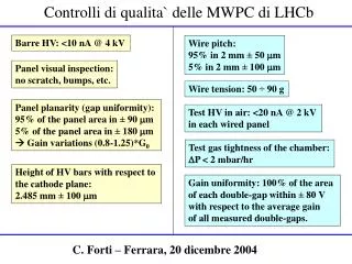
Controlli di qualita` delle MWPC di LHCb Barre HV: <10 nA @ 4 kV Wire pitch: 95% in 2 mm ± 50 mm 5% in 2 mm ± 100 mm Panel visual inspection: no scratch, bumps, etc. Wire tension: 50 ÷ 90 g Panel planarity (gap uniformity): 95% of the panel area in ± 90 mm 5% of the panel area in ± 180 mm Gain variations (0.8-1.25)*G0 Test HV in air: <20 nA @ 2 kV in each wired panel Test gas tightness of the chamber: DP < 2 mbar/hr Height of HV bars with respect to the cathode plane: 2.485 mm ± 100 mm Gain uniformity: 100% of the area of each double-gap within ± 80 V with respect to the average gain of all measured double-gaps. C. Forti – Ferrara, 20 dicembre 2004 The measure of the gas leakage, is obtained by correcting the DP(t) behavior by using the data of the reference chamber.
Check of HV bars and effects on HV test in air • Since few months we check all the HV bars: • visual inspection (we found broken R,C); • cleaning; • HV test: we require < 10 nA @ 4 kV. Since we found a consistent fraction of bars drawing current, we changed the procedure: now Sei System send us the bars without conformal coating. Another (much better) company performs: cleaning; drying (in hoven); putting conformal coating.
Check of panel planarity • According to simulations (Riegler), the requirements on the gain: • G0/1.25 < G < G0*1.25 over 95% of the detector area • G0/1.50 < G < G0*1.50 over 5% of the detector area • where G0 is the nominal gain translate into the following requirement: • Gap = 5 mm ± 90 mm (95% of detector area) ± 180 mm (5% of detector area) Since the gap is provided by the 5mm spacers placed between the panels, along their frames, the gap uniformity is related to the uniformity of the panel thickness and to its planarity. The absolute value of the panel thickness is crucial only when a panel is wired on both sides (CERN and PNPI), because the distances between the wire planes and the panel surfaces depend on thickness. The requirement is T=9.0 ± 0.2 mm
Manual check of planarity A check of panel planarity is performed in each site on ALL panels , before gluing the HV bars. 50 mm planarity < 90 mm (95% of detector area) < 180 mm (5% of detector area)
Panel Laser Beam d1 d2 Thi D Thi = D-d1-d2 Panel measurement table Status report (R. Messi/E.Santovetti) Measurement scheme The system appear to be extremely solid and precise The measurement of each point is repeatable at the level of ~ 10 m RMS ~ 3m Max-min ~ 12m
Gas leakage test (I) In order to minimize the gas refill rate, the maximum leakage allowed for each chamber is 2 mbar/h. To verify the gas tightness of a chamber, we inflate it with nitrogen up to an overpressureDP of 5 mbar. Then, we recordDP as a function of time, during about one hour. The measurement is sensitive to variations of the external temperature. In order to correct this effect, a second chamber is used as a reference. The measure of the gas leakage, is obtained by correcting the DP(t) behavior by using the data of the reference chamber.
Gas leakage test (II) The measure of the gas leakage, is obtained by correcting the DP(t) behavior by using the data of the reference chamber. If a chamber leaks, usually we can recover it by putting glue all around the chamber, between each pair of panels. For ex. In LNF, over 73 chambers produced, only one was not recovered. The measure of the gas leakage, is obtained by correcting the DP(t) behavior by using the data of the reference chamber.
Wire pitch measurement (I) The wire position is precisely determined by the pitch of the wiring machine combs, however it is important to check that no wire is out of the acceptance. The requirement on the wire pitch (WP) is: WP = 2 mm ± 50 µm (95% of pitches) ± 100 µm (5% of pitches) The WP measurement is performed with anautomatic device, based on two cameras scanning the panel and a software for image acquisition and analysis. An accuracy of about 20 µm is obtained. Sample image from scanning device The measure of the gas leakage, is obtained by correcting the DP(t) behavior by using the data of the reference chamber.
Wire pitch measurement (II) The range 2 mm±50 µm corresponds to the red lines drawn at 211 ± 5 pixels. For example in LNF, over all chambers produced (~180,000 wires), we changed only few wires with wrong pitch. The fraction is somewhat higher at CERN, where the wires touch the HV bars, but this is not a cause of worry. The measure of the gas leakage, is obtained by correcting the DP(t) behavior by using the data of the reference chamber.
Wire tension measurement (LNF) The wire mechanical tension must be in the range 50÷90 g in order to provide a good electrostatic stability. The wire tension t can be found by measuring its mechanical resonance frequency n0with the formula: l : mass per unit length of the wire l: length of the wire To measure n0, mechanical oscillations of the wire to be tested are induced by applying a periodic high voltage (about 900 V) with a frequency of 300 ÷ 400 Hz, between this wire (Cw) and a non-oscillating sense (Sw) wire placed parallel and close to it at a distance d of about 1 mm. The capacitance C between the two wires is given by: where a and b are radii of wires and l is the SW length. LNF method The measure of the gas leakage, is obtained by correcting the DP(t) behavior by using the data of the reference chamber.
Wire tension measurement (LNF) The oscillations result in a variation of C. The maximum variation of C occurs at the mechanical resonance of the chamber wire. A resolution of about 1 g is obtained and a M3R3 panel (660 wires) can be checked in less than 1 hour. LNF method The measure of the gas leakage, is obtained by correcting the DP(t) behavior by using the data of the reference chamber.
Photodiode Laser Mechanical excitation wire Panel Wire Tension Measurement in FE This method has been developed together with Firenze and Roma II The signal is sent to a PC’s soundcard, a FFT is applied and the fundamental frequency is searched between 310 and 600 Hz (for M2R3 panels)
Photodiode Laser Mechanical Excitation Wire Tension Measurement in FE The measurement takes about 2 sec/wire (2 panels ~1200 wires in 40 min)
Gain average and uniformity The goal: to have all detector area within the HV plateau defined by the mimum efficiency and by the maximum cluster size M1: the chamber is a double-gap; the efficiency must be e > 99% The double-gap average n. of hits must be < 1.2 M2-M5: the chamber is a 4-gap; the efficiency of each double-gap must be e > 95%. The 4-gap average n. of hits must be < 1.2 From testbeam of LNF chambers, these requirements define the following 170 V wide regions: M1: 2720 ± 85 V M2-M5: 2620 ± 85 V
New criteria on gain average and uniformity Each double-gap is classifiedin A,B,C classes according to: A. < I(2-gap) >/1.4 < I(i) < < I(2-gap) >*1.4 (equivalent to ± 50 V range) B. < I(2-gap) >/1.7 < I(i) < < I(2-gap) >*1.7 (equivalent to ± 80 V range) C. Requirement B not satisfied DV > 80 V The conditions above are required on 100% of the double-gap area. For each double-gap, we provide the class: A = 100% of double-gap area in DV<50 V B = 100% of double-gap area in DV<80 V C = not satisfying criteria A and B Chamber class: AA,AB,BA=GOOD BB=SPARE BC,CB,CC=RESERVE
Current (nA) Y position in the gap X position in the gap 137Cs source case Test with radioactive source (LNF) Uniformity of the gapgain is tested with a40 mCi 137Cs source. The current drawn by each gap is monitored while the lead case containing the source is moved by means of a mechanical arm. These measurements allow to check the gain uniformity within each gap and to compare different chambers among them. Profile view of a MWPC on thesource test table. Example of a result of the scan with radioactive source The measure of the gas leakage, is obtained by correcting the DP(t) behavior by using the data of the reference chamber.
Chamber production Overview You're logged in as lhcb Shows chambers. Last update: December 17, 2004, 3:21 pm M5R3 Chamber 14 LNF results: 58 chambers M3R3: 1 leaks; 1 broken wire @ GIF (?); 39 AA; 13 AB/BA; 4 BB 15 chambers M5R3: all AA
Test of Ferrara chambers @ Roma2 Source Sr90 8 mCi electrons of ~2.5 MeV Collimated ~2 mm diameter
Test of Ferrara chambers @ Roma2 A BCD ABCD Rosso:misura tra 2 pad Nero e verde: al centro di ogni pad
Test of CERN chambers with radioactive source • 241Am source
Delay line (TDC) and ADC output • All anodes connected together ADC Amplitude spectrum • Cathode connected to the delay line TDC Pad location Delay line output ADC spectrum Time (ns)
Gas Gain Map Example of a map of the ADC peak For each pad of each gap Test station is operational Six chambers tested Gas gain RMS is ~10 % for all chambers
Test with cosmic rays (LNF) • The use of a cosmic ray stand allows to measure: • efficiency • time resolution • average hit-multiplicity • electronics noise • The system allows to house and test up to six chambers simultaneously (600 channels). The trigger is given by three large scintillators (one above and two below the chambers) read out on both sides.The trigger rate is of about 15 Hz and its time resolution is about 2.8 ns. time spectrum We tested only few chambers, because we do not have still the final FEE. We plan to test all (or part of the) chambers, after the final FEE and the Faraday cage will be mounted on them.This is still under discussion. The measure of the gas leakage, is obtained by correcting the DP(t) behavior by using the data of the reference chamber.
Laser beam d1 D2=Kost Thi Thi = 9.13mm Test of guides precision 38 vertical scans on 16 fixed points (mesurements on two different days
Plateau width (M2-M5) From testbeams: plateau width=170 V for bigaps; 150 V for 4-gaps Lower plateau limits: 95% for bigap (2.53 kV) / 99% quadrigap (2.55 kV) Upper limit: cluster size in quadrigap < 1.2 HV <2.7 kV (calculated from oct’03 results on the bigaps) 2.62 ± 0.075 kV 99% Testbeam oct. ’03: BIGAP GIF july ’04: 4-GAP
Plateau width (M1) FROM OCT’03 (BIGAP): Upper limit: cluster size =1.2; in bigap HV~2.82 kV FROM GIF: Lower plateau limit: e=99% in double-monogap HV=2.65 kV Work point ~ 2.72 kV Plateau width ~ 170 V Testbeam oct. ’03 : BIGAP GIF july ’04: DOUBLE-MONOGAP