
Wedge Flow Element
Wedge Flow Element. V - Shaped Restriction. No critical surface dimension Slanted upstream and downstream faces No places for secondary phase build-up Minimal upstream/downstream piping required Bi-directional. Simple Design - Easy to Understand. No Moving Parts. P1. P2.
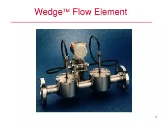

Wedge Flow Element
E N D
Presentation Transcript
V - Shaped Restriction • No critical surface dimension • Slanted upstream and downstream faces • No places for secondary phase build-up • Minimal upstream/downstream piping required • Bi-directional
Simple Design - Easy to Understand • No Moving Parts P1 P2 Wedge Flow Element Q P
Wedge Flow Element V1 V2 P1 P2 Permanent Pressure Loss
Wedge Flow Element Physical Attributes Dirty Service Chem Tee (Flush Mtg.) (1630LF) 3” Flange Tap Connection (1630LF)
WEDGE Flow Element Physical Attributes Clean Service 1/2" NPT Connection Pipe Tap Connection (1610LF) 1/4" NPT Direct Connect Integral WEDGE (1335LZ-1337LZ) Wafer Water & Gas Injection (1615LW)
H/D Ratio of 0.2 0.3 0.4 0.5 D H Wedge Characterized by H/D to Handle Different Flow Ranges Determining beta ratio d/D: Orifice Plate: d=orifice bore diameter, D=pipe inside diameter Wedge equivalent beta ratio for H/D ratio selected: for H/D Ratio of use ß 0.2 0.38 0.3 0.50 0.4 0.60 0.5 0.70
The Wedge Element Advantage Flexibility and Adaptability Wedge Element Wedge Element DP Transmitters Process Conn. Materials Connections • 316 SS • Carbon Steel • Hastelloy1 alloy* • Monel2 alloy* • Other exotics • Threaded • Flanged • Wafer • Direct connected • Pipe tap • Remote seal elements * Available upon request 1 Trademark of Cabot Group 2 Trademark of Huntington Alloy, Inc., The International Nickel Company, Inc.
The Wedge Element Advantage • Lower permanent pressure losses than orifice plate mean lower pumping costs for the life of the installation 100 - 90 - 80 - 70 - 60 - 50 - 40 - 30 - 20 - 10 - Orifice Plate Pressure Loss % of Meter Differential Flow Nozzle Wedge 0.2 0.3 0.4 0.5 0.6 0.7 0.8 0.9 Beta Ratio
KD 2 Calibration Performed with Water .920 .900 20,000 25,000 30,000 35,000 40,000 45,000 50,000 Pipe Reynolds No. RD Typical Linear Curve (Low Reynolds Number) 1-1/2” (40mm) Pipe Size 0.4 H/D KD 2 Calibration Performed with Glycerine .940 .920 .900 .880 .860 .840 200 400 600 800 1000 1200 1400 1600 1800 Pipe Reynolds No. RD
Typical Linear Curve (High Reynolds Number) 3” (75mm) Pipe Size KD 2 .3H/D Water - Average KD 2 = 1.773 Air - Average KD 2 = 1.772 2.20 2.00 1.80 1.60 .2H/D Water - Average KD 2 = 1.005 Air - Average KD 2 = .995 1.40 1.20 1.00 .80 0 100 200 300 400 500 600 700 800 900 1000 Pipe Reynolds X 1000
Performance Evaluation Upstream Piping Effects
Wedge Family of Problem Solving Flow Elements • Wedge elements are available in standard sizes of 1/2” to 24” (larger sizes available) • Pipe tap, wafer and integral Wedge elements for clean liquids, gases and steam • Remote seal Wedge elements for all fluids - clean, dirty, viscous, corrosive or erosive • Wag Wedge for Wafer and Gas Injection Systems for oil field recovery • Integral Wedge elements connect directly to DP transmitters
When to Use the Wedge • Chemical industry - Batching, blending, mixing dyes and viscous fluids • Petrochemicals - High viscosity and black liquors • Oil and Gas - Water injection, custody transfer • Paper and Pulp - High concentration stocks. Timber industry usage • Metals and Mining - Powdered or magnetic slurries. Abrasive flows • Cement industry - Problematic slurry flows • Power and Utilities - Fuel oil and steam flows. Boiler feeds
WedgeMaster Connections 3” (76mm) Flange Tap Connection 1630LF Chemical Tee Connection 1630LF
WedgeMaster Flow System • Base System Accuracy: 0.5% • Draft Range Designed for Intended Purpose • HART Digital Communications • 5 Year Warranty • Inductive Sensing • sensing & correcting of sensor temp and static press • Surface Mount Electronics • Local Zero & Span • Configures From KHT & KSSW
Comparison Wedge vs Orifice Plates • Disadvantage • Less Application History • Initial installed cost • Advantage • Lower Reynolds No. • Better Rangeability • Accuracy not Dependent on Sharp Edge • Lower Energy Costs • Five Year Warranty • Less upstream piping required • Dirty Service (Slurries, Fluids w/Solids in Suspension)
Wedge vs Orifice Plate • Specification • Accuracy • Turn Down • Reynolds No. • Output • Sizes • Straight Upstream Piping Wedge 0.5% 4:1 >500 square root 1/2”- >24”(15 ->600mm) 6 Diameters Orifice 0.75% 4:1 >30000 square root >1” (>25mm) 15-30 Diameters
Comparison WedgeMaster vs Turbine Meter • Advantage • No Moving Parts • Corrosive, Dirty Fluids • Viscous Fluids • Less Pressure Loss • Disadvantage • Non-linear Output
Wedge vs Turbine Meter Turbine 0.5% 10:1 >30000 linear 1” - >12” (25 - >300mm) • Specification • Accuracy • Turn Down • Reynolds No. • Output • Sizes WedgeMaster 0.5% 4:1 >500 square root 1/2” - >24” (15 - >600mm)
Comparison Wedge vs Vortex • Advantage • Low Reynolds No. • Viscous Fluid Applications • Requires Less Upstream/ Downstream Diameters • Better Accuracy • Slurry Applications • Disadvantage • Accuracy Affected by Density • Non-linear Output
Wedge vs Vortex • Specification • Accuracy • Turn Down • Reynolds No. • Output • Sizes • Straight Upstream Piping WedgeMaster 0.5% 4:1 >500 square root 1/2”- >24” (15 - >600mm) 6 Diameters Vortex 1.0% + 10:1+ >10000 linear 1” - >10” (25 - >250mm) 10-30 Diameters
Comparison Wedge vs Positive Displacement • Disadvantage • Non-linear Output • Greater Piping Requirements • No Custody Transfer Applications • Advantage • Much Lower Cost • No Moving Parts • Lower Pressure Loss • Slurry Applications • Steam and Dirty Gas Applications
Wedge vs Positive Displacement WedgeMaster 0.5% 4:1 >500 square root 1” - >24” (25 - >600mm) • Specification • Accuracy • Turn Down • Reynolds No. • Output • Sizes P. D. 0.5% + 20:1 variable linear 1” - >12” (25 - >300mm)
Comparison Wedge vs Mass • Advantage • Lower Cost • No Moving Parts • Lower Maintenance • More Line Sizes • Not Affected By Vibration • Disadvantage • Non-linear Output • Less Accurate • Affected by Fluid Properties