Download
1 / 34
340 likes | 356 Vues
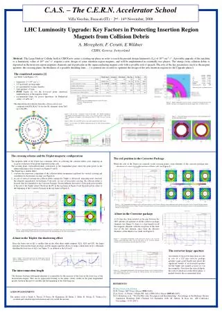
This option explores the use of water cooled cables for the corrector package, considering the installation location and power cable routing requirements. It also provides an estimate of operational costs and the need for additional provisions.

E N D
Option to feed the Corrector Package correctors with Water cooled cable following TCC 01/11/2018 G. D’Angelo, P. Fessia, J.-C. Guillaume, S. Yammine, F. Rodriguez Mateos
Short summary • TCC endorse the removal of the 120 A and 200 A SC wires from the SC link • The connection of the CP (where the related magnet are connected) to the PC and the PC location itself is still pending • The following options were discussed • Case A: use to standard warm cable leaving the PC on the HL UR. The cables would run through the HL ULs and SC link core. This had to be reviewed because the core modification to allow the warm copped cable to cool in air and the CV installation in the UL had not been foreseen • Case A’: the update version of the Case A • Case B: installation of the PC in the LHC service galleries around the IPs • On the 01/11/2018 following the presentation it was asked to analyze the Water Cool Cable option Case A’’ To edit speaker name go to Insert > Header & Footer and apply to all slides except title page
Plus saving in magnet test (not quantified) Op. cost electricity between 15 to 45 kCHF over 10 years (depending from kWh cost). Indicative evaluation WP6b TCC 01/11/2018 Op. cost + 80 kCHF Provision in case of need (38 kCHFalready in baseline) To edit speaker name go to Insert > Header & Footer and apply to all slides except title page
Option 2 : POINT 1 IP1 L IP1 R P8 P2 LEFT IP1 RIGHT 238.1 M 238.1 M 207 M 207 M 19 19 UJ14 UJ16 RB26 UJ17 RR13 UJ13 RI171 RI132 RB14 RR17 53.3 53.25 156.7 156.7 Q4 Q6 D1 Q3 Q5 D2 Q2A Q4 Q5 Q3 Q2A Q6 D2 D1 Q1 Q2B Q2B Q1 CP CP UA13 79.75 M HL_LHC machine UL13 UA17 UL17 UL16 UL14 US17 OUVRAGE LHC IMPACTED UR15 94.25 M 94.25 M 53.69 M • 1 rack spare • contrôle (RYSC01) • 3 racks PC 120 A • (R2E design) , (8 pc). Baseline location (140 m cables) • 2 racks sparemodules • (RYSA01-RYSA02) 1 rack PC 200 A (R2E-LHC600A-10V) Location to place PC @LHC zone ½ rack energie extraction for 200A 1 rack
IP1 R 8 racks It’s possible ! F • HL_LHC STUDY UJ16 QH : 14 racks TYCFL01 SPARE 2 SPARE 3 BY01 QYC01 QYC02 TYCFL01 RYSA01 RYSA02 UL16 Debitmetre DFBX EXISTING LHC Interlock rack CYCIP01 Displace geophone Not recommended! GEOPHONE • 2 racks sparemodules • (RYSA01-RYSA02) ½ rack energie extraction for 200A 1 rack GEOPHONE 1 rack PC 200 A (R2E-LHC600A-10V) • 3 racks PC 120 A • (R2E design) , (8 pc). View along F UJ16 • 1 rack spare • contrôle (RYSC01) EXISTING LHC RACKS QYC03-04 UL16 (As now) QH : Quench heaters power supplies
IP1 L 8 racks It’s possible ! Q3 Q1 Q2A • HL_LHC STUDY Q2B UJ14 TYCFL01 SPARE 2 SPARE 3 BY01 QH : 14 racks QYC01 QYC02 TYCFL01 RYSA01 RYSA02 EXISTING LHC Interlock rack CYCIP01 ½ rack energie extraction for 200A 1 rack TRANSPORT AREA • 2 racks sparemodules • (RYSA01-RYSA02) 1 rack PC 200 A (R2E-LHC600A-10V) • 3 racks PC 120 A • (R2E design) , (8 pc). UL14 Variante possible also ! EXISTING LHC RACKS QYC03-04 • 1 rack spare • contrôle (RYSC01) (As now)
Power cables routing from PC to CP IP1 R This part of the routing have to be studied more in details EXISTING CORES UJ16 UL16
Option 2 : POINT 5 IP5 L IP5 R P4 P6 IP5 RIGHT LEFT 238.1 M 238.1 M 207 M 207 M 19 19 RZ54 R561 UJ56 R562 RR53 UJ57 R571 R542 R532 UJ53 RR57 R541 127.1 93.6 22 30 88.4 25.1 25.1 Q4 Q5 Q6 D2 Q2A Q4 Q3 D1 D2 Q6 Q3 Q5 D1 Q2A Q2B Q1 Q2B CP Q1 CP UA53 79.75 M UA57 HL_LHC machine USC55 UL57 US57 UL557 UL53 OUVRAGE LHC IMPACTED UR55 53.69 M 94.25 M 94.25 M Baseline location (140 m cables) Location to place PC @LHC zone
Option 2 : 8 racks It’s possible ! PLACE 14 QH racks in UJ56 IP5 R • 1 rack spare • contrôle (RYSC01) ½ rack energie extraction for 200A 1 rack (As now) • 3 racks PC 120 A • (R2E design) , (8 pc). 1 rack PC 200 A (R2E-LHC600A-10V) • 2 racks sparemodules • (RYSA01-RYSA02) (As now) UL557 Free space !
Option 2 : ½ rack energie extraction for 200A 1 rack IP5 L USC55 8 racks It’s possible ! QH : 14 racks • 1 rack PC 200 A • 3 racks PC 120 A • 1 rack spare • contrôle (RYSC01) (As now) • 2 racks sparemodules • (RYSA01-RYSA02) (As now) Free space (3 racks)
Power cables routing from PC to CP IP5 R UL557 UL56 ≈ 70 M UP56 R562 D1 PM56 CP Q3 UJ56 Q2B Q2A
Power cables routing from PC to CP IP5 L USC55 UL54 ≈ 80 m RZ54 R541 D1 UP53 CP Q3 Q1 Q2B Q2A
WCC To edit speaker name go to Insert > Header & Footer and apply to all slides except title page
≈ 30 m UL17 RI171 UJ17 ≈ 50 m ≈ 10 m Max length of power cables ≈ 115 -120m UL17 ≈ 25 m UR15 RI171
For HL-LHC: DC water cooledlines 200 and 120A LHC tunnel ACC ACC Water distribution Technical solution: Termination ACC: Air cooledcables WCC: Water cooledcables WCC: Length/pol ~ 120m (X 9 per half point = 2160m/half point => total: 8640m ) UR -> door in UL UL Core Converter CP Installation in cabletrays Exemple Termination
Some consideration on ELQA and space • We would have a WCC cable length per circuit between 200 m and 250 m • This would lead to a leakage current > > 100 µA per circuit to be compared with the typical 5 µA that need to be measured (1µA for MCBCcircuits → 10µA for MCBY) • Human intervention in the LHC tunnel will be necessary to act on the junction box between the WCC and the standard cable that will be connected to the current leads on the CP • The junction box will be near the D1, a complex area with not negligible radiation (much larger respect the UJs and ULs) To edit speaker name go to Insert > Header & Footer and apply to all slides except title page
To be developed and not costed here For HL-LHC: DC water cooledlines 200 and 120A ACC ACC Water distribution Technical solution: Termination ACC: Air cooledcables WCC: Water cooledcables WCC: Length/pol ~ 120m (X 9 per half point = 2160m/half point => total: 8640m ) UR -> door in UL UL Core LHC tunnel Converter DFX Installation in cabletrays Exemple Termination Advantage: 0%->10% of thermal loads remaining in the UR, UL, cores and LHC tunnel. Disadvantages: High bending radius for the cables, risk of crushing the cable during installation, special manufacture need more place -> C. trays more larger. Need of water -> risk of water leakage -> Water interfaces Need interlock cable to verify that the cable is correctly cooled. Price: High level. Ex: Pt 3 LHC: 800A; 3 lines DC 500mm2 WCC from UJ32 -> SS pt3: 4.5 km; price 0.9 MCHF @2005 ~ actually: 1.2 MCHF (260CHF/m) For 200A: 36 lines 120mm2 (~100CHF/m) and 8.64km: -> 0.8 MCHF (very preliminary approach).
Plus saving in magnet test (not quantified) Op. cost electricity between 15 to 45 kCHF over 10 years (depending from kWh cost). Indicative evaluation WP6b Op. cost + 80 kCHF Provision in case of need (38 kCHFalready in baseline) To edit speaker name go to Insert > Header & Footer and apply to all slides except title page
Previous presentation 01/11/2018 To edit speaker name go to Insert > Header & Footer and apply to all slides except title page
Necessary actions and impact evaluations to leave the 120 A and 200 A PC (correctors in the CP) in the HL-LHC UR gallery F. Borralho, A. Broche, P. Cardon, P. Fessia, J.C. Guillaume, S. Maridor, M. Martino, P. Mattelaer, A. Mejica, S. Yammine. F. Rodriguez Mateos
Amalia Ballarino et al. TCC 20/09/2018 Cost evaluation Plus saving in magnet test (not quantified) Operational cost + 80 kCHF Provision in case of need Total saving CASE A:575 kCHF CASE B: 550 kCHF Total extra-cost CASE A: 425 kCHF CASE B: 232 kCHF Net saving CASE A:150 kCHF CASE B: 318 kCHF
Case definition • CASE A: • PC installed in the HL UR • Connection to the CP via copper cables in the HL UL via vertical cores • No solution for cooling of the cable in the cores • CASE B: • PC installed in the LHC Point 1 and Point 5 bypasses as the present IT PC (LHC ULs) • Connection following similar path as the present cables for the DFX • CASE A’: • Refined CASE A with solution for the cooling of the cables in the cores To edit speaker name go to Insert > Header & Footer and apply to all slides except title page
Actions to make feasible the installation of the 120A and 200 A in the UR linking them to the CP with copper cable • Find solution to provide cooling to the cables installed in the vertical cores • Optimize PC position to reduce the cable length and reduce integration problems in the UR • Check that introduced resistance is acceptable for the circuit • Ensure that the dissipated heat power can be evacuated Review of the Case A with more details and associated Cost. Here as Case A’ To edit speaker name go to Insert > Header & Footer and apply to all slides except title page
4 racks P1@RIGHT DFHX_2 DFHX_1 DFHM US17 UR15 UL17 SCLINK VALVES BOX UJ17 Q1 COLD BOX Q2A Q2B Q3 CP RI171 D1 UA17 DFX UPR17 D2 (DFM) CC RR17 Q4 Q5 Q6
≈ 30 m UL17 RI171 UJ17 ≈ 50 m ≈ 10 m Max length of power cables ≈ 115 -120m UL17 ≈ 25 m UR15 RI171
UL17 Pc 120 A / 200A UL17 UR15
400 x100 SCLINK UL17
RI171 RI171
RI171 D1 UJ17 CP
Moving surface for air leak tightens from UL to LHC tunnel The proposed solution satisfies EL requirement Modifying 4 cores (1 each IP Side). WP17.1 estimated cost 32 kCHF/core Total 128 kCHF Images shown here on the left are purely conceptual and have been prepared by WP15. They are not representative of th possible solution to be proposed by WP17.1 Remark the flat enlargement at the bottom of the core would help the installation of the new DFX To edit speaker name go to Insert > Header & Footer and apply to all slides except title page
WP6B position • There is no technical showstopper to keep the PCs in the URs. The supplement with respect to the baseline (120 A and 200 A in the sc link) will + 0 CHF for URs vs + 75 KCHF for ULs/USC55 . • WP6B has communicated the requested minimum cable sections to EL (for 120A and 200A circuits) that respect the power converters limitation of 10V. This takes into account the ramp rate requirements given to us by WP2 and an estimate of the cables length (140 m per polarity). The new increased inductance value of the Quad Corrector (1505 mH vs. 1247 mH before) remains in the margin that has been taken. • The margin taken on the voltage is 20 % and accounts for inductance variation in function of circuit current, possible mutual inductances between circuits, possible inductance evolution from magnet design perspective, etc. • The indicative cable cross-sections provided by EL to satisfy the WP6B requirements are are: • 200A : 240 mm2/polarity • 120A : 120 mm2/polarity To edit speaker name go to Insert > Header & Footer and apply to all slides except title page
WP 17.2: cabling • With the previous sections and 120 m the budgeted cable cost is 81 kCHF/IP side • Total 324 kCHF • Possible cost increase for installation in the cores To edit speaker name go to Insert > Header & Footer and apply to all slides except title page
WP17.3: cooling and ventilation 2.3 kW UL • With the maximum current the following power shall be dissipated • Vertical cores: 0.4 kW • UL ventilation door to core: 1.9 kW • UR:1.1 kW • It is needed to install 2 water cooled Fan-Coil in each UL (1+1 redundant). No water drainwas foreseen in the ULs. Small risk in case if water leak:costs 40 kCHF/UL fan coil 10 kCHF/UL collectors (partial compensatory measure) TOTAL 200 kCHF The 2 DN20 pipes to feed the Fan-Coil shall be integrated in the same trench with the SC link Power to be extracted matching full power max current To edit speaker name go to Insert > Header & Footer and apply to all slides except title page