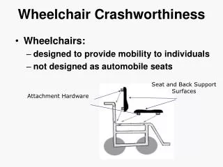
Automated Wheelchair Design and Development: A Comprehensive Engineering Approach
280 likes | 397 Vues
This project presents the design and development of an automated wheelchair, guided by Mr. Rathinam, a senior lecturer at SRM Engineering College. It covers mechanical design, motor selection, circuit schematics, and software control algorithms. The wheelchair accommodates a maximum weight of 200 kg, achieving an average speed of 3 km/h. Key features include user-friendly direction control, a compact design, and provisions for manual steering and basic obstacle detection. Future enhancements are discussed, like integrating solar power and remote control functionalities.

Automated Wheelchair Design and Development: A Comprehensive Engineering Approach
E N D
Presentation Transcript
Automated Wheelchair Done By HARIHARAN L KARTHIKEYAN S P NARESH S LAKSHMI V Guided By Mr. RATHINAM A Senior lecturer SRM Engg. College é é
é Contents • Introduction • Mechanical design • Selection of motors • Circuit design • Software • Conclusion • Future scope
é Top view of set up gear • Proper Weight balance • Dead weight = 50 kg • Plank size: 80 x 40 cm plank M supply processor Control circuit 80 cm wheel Battery 2 M G Battery 1 chair 40 cm
é Mechanical Design • Gears • Back wheel setup • Front wheel setup • Formulae Used/ Calculation • Braking
é Gears Spur Gear Worm Gear Bevel Gear
é Back Wheel Setup
é Front Wheel Setup
é Formulae Used V = 3.14xDxNw/60 Pw =2x3.14xNwxTw/60 Tw = 9.81xWxR where V => Linear Velocity Pw => Power of Motor Tw => Torque of the Wheel Shaft D => Diameter of wheel Nw => Speed of wheel
é Back Wheel Calculation Speed of wheel (Nw) = 50rpm Diameter of wheel (D) = 32cm Linear Velocity (V) = 3.14 x 32 x 10-2 x 50 / 60 = 0.837m/s (3Kmph) Power of Motor (Pw) = 120W Speed of the motor shaft =3000rpm Diameter of Motor Shaft(d) = 9mm Maximum Torque in Motor shaft = 0.382Nm Assuming 75% efficiency for the worm wheel gear, a gear ratio of 1:60, Torque of the Wheel Shaft Tw = 60 x 0.382 x 0.75 = 17.18Nm Radius of the wheel Shaft Rw = 9mm Maximum Weight that it can withstand Wmax = 17.18/(0.9x10-2x9.81) = 194.59 kg (approx 200 kg)
é Braking • Worm Gear -Serves Dual Purpose • Property: • Torque improvement • Irreversibility • Instantaneous braking
é Selection of Motors • Reasons for selecting PMDC • Reasons for selecting Servo Motor • Motor Ratings • Vehicle Testing
é PMDC Reasons for selecting PMDC • Efficiency of PMDC > Efficiency of DC Motor • Smaller size of PMDC than DC for same Power • Less voltage => Less noise • Less Radio or TV interference • Lower manufacturing cost
é Servo Motor Reasons for selecting Servo Motor • Low inertia due to the fact that armature mass is less • Fast torque response • Step change in armature voltage or current produces quick change in position or speed of the rotor
é Motor Ratings SERVO MOTOR Voltage: 24V Current: 1.25A Torque: 1.5KgCm PMDC Voltage: 24V Current: 7A Power Rating: 120W Speed: 3000rpm
Loading Condition Voltage Applied (V) Current Drawn (A) Wheel Speed (RPM) No Load Reading During Straight run 24 4.5 60 During Turning 24 5.5 50 Load Reading During Straight run 24 7 50 During Turning 24 9 40 é Vehicle Testing
é Circuit Design • H-Bridge Control of Motor • Control Box • Block Diagram • 8085 Based Relay Control Circuit
é H-Bridge Forward Direction Supply (positive) relay3 – motor – relay4 Supply (negative) Reverse Direction Supply (positive) relay1 – motor – relay2 Supply (negative)
é Control Box Forward Left Right Start/Stop Head lamp Horn Reverse
é Block Diagram Port C 8255 interfaced with processor Control box 8085 Microprocessor Port A & B Control circuit
Control é Circuit
é Software Control Logic Algorithm Flow Chart
é Control Logic
é ALGORITHM Step1:Configure Peripheral Programmable Interface (PPI-8255) as the following: Port A => Output Port Port B => Output Port Port C => Input Port Step2: Initialize Stack Pointer Step3: Begin scanning the commandsissued by the user. Step4: Check for the position of the start/stop switch If in Start position Begin scanning other inputs Else Go to Step1 Step5: Check whether Forward Key is pressed. If pressed Go to Forward subroutine Else Go to next step
é continued. • Step6: Check whether Reverse Key is pressed. • If pressed Go to Reverse subroutine • Else Go to next step • Step7: Check whetherLeftKey is pressed. • If pressed Go to Left subroutine • Else Go to next step • Step8: Check whether RightKey is pressed • If pressed Go to Right subroutine • Else Go to next step • Step9: Go to Step3 for scanning inputs again
é FLOW CHART Y N Note: Main Switch =>ON Other Operations carried out Y N Y N Y N N Y
é CONCLUSION • Some salient features about our vehicle are • User friendly. • Proper direction control (automatic steering system). • Additional manual steering. • Designed to withstand a weight of a normal human being. • Designed to run at an average speed of 3kmph. • Compact design (hind wheel set up is fitted underneath the plank). • A horn facility (as in any normal vehicle).
é FUTURE SCOPE • Some of the additional features that can be implemented are • Replace Microprocessor by Microcontroller. • Remote control to operate from anywhere. • Predefined motion to facilitate parking etc. • A light dependent headlight (for easy propagation in the dark as well) and Obstacle detector. • Replace batteries by a Solar Panel.