Download
1 / 52
720 likes | 1.15k Vues
VLF LF MF and HF ANTENNAS. CLASSIFICATION ACCORDING TO FREQUENCY BANDS. VLF/LF Antennas and Antenna Systems. VLF Band . EM waves penetrate well in to the sea water . (Communications with submerged submarines) Low atmospheric attenuation .

E N D
VLF LF MF and HF ANTENNAS CLASSIFICATION ACCORDING TO FREQUENCY BANDS
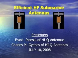
VLF Band • EM waves penetrate well into the sea water. (Communications with submerged submarines) • Low atmospheric attenuation. • Appropriate for long range communication.
VLF Antennas • Ground and Sky waves • Frequeny range: 3-30 KHz • Antennas : very large • Power: kW levels and even more
Some Problems Associated with VLF Antenna Systems • Small Bandwidth (usually less than 200 Hz) • Small radiation resistance. • High cost. • Antenna system covers a large area. • Need for very high power levels for transmission.
LF Antennas • Ground and Sky waves • Frequeny range: 30-300 KHz • Antennas: large • Power: kW levels and even more
Some Disadvantages • High cost • Large Dimensions • Trouble with efficiency, power capacity, bandwidth
VLF and LF antennas are “electrically small” antennas : • problem: high capacitive reactance and small antenna radiation resistance • remedy: top loading
Top-loading • Top-loading increases gain bandwidth (by decreasing reactance) • In VLF large top-loading supported by towers
VLF / LF Ground Systems • Radial-wire: radial wires buried in the ground • Multiple-star: small radial-wire systems forming a star topology
Vertical Electric Monopole Antenna Assume uniform electric current I along a vertical monopole of effective height he : electric field magnetic field
Vertical Electric Monopole Antenna-Radiated Power- The vertical electric field in terms of radiated power is:
Vertical Electric Monopole Antenna-Equivalent Antenna Circuit-
Vertical Electric Monopole Antenna(Radiation Efficiency) and where antenna total loss resistance Effective power = (power capacity of the transmitter) x (antenna system efficiency)
Vertical Electric Monopole Antenna-Antenna Bandwidth- The 3 dB bandwidth b in (c/s) for a single resonant circuit is: f : resonant frequency Q: the circuit reactance resistance ratio X/R0 R0: Total series resistance
Multiple Tuned VLF Antennas To have sufficiently large bandwidths: • Huge antenna systems must be built. or • Several small multiple-tuned elements must be be used.
Multiple Tuned VLF Antennas • Ground losses are reduced. • Radiation resistance and efficiency are increased. • Instead of one and vulnerable antenna, several and smaller elements can achieve the same bandwidth-efficiencyproduct. • If one element is out of service, the others can still operate. • The effective ground loss with multiple-tuning will be less than for a single element. • Tuning and retuning the system is difficult. • each antenna has to be matched to the transmitter.
References (1) “VLF Radio Engineering”, A. D. Watt, Perg. Press, 1967 (2) “High Power Very Low Frequency/Low Frequency Transmitting Antennas”, P Hansen, Military Communications Conf., 1990. MILCOM '90, Conference Record, 'A New Era'. 1990 IEEE, 30Sept.-3Oct.1990 Pages:1091 - 1096 vol.3 (3) Technology Conference, 1991.IMTC-91.Conference Record. ,8th IEEE , 14-16 May 1991 Pages:330 - 334 (4) “Multiple Tuned VLF Antennas”, Manfred Schopp, IEEE Transactions on Broadcasting, Vol. 39, No.4, Dec. 1993. References for the photos & figures: [1] http://hawkins.pair.com/nss.shtml [2] http://www.tpub.com/neets/book17/77.htm
INTRODUCTION • Usually: Vertical radiators operating in the MF band (300-3000 kHz). • The towers may be guyed or self-supporting.
APPLICATION AREAS • AM Broadcasting • Maritime Radio • Coast Guard Communication • Direction Finding
CHARACTERISTICS OF RADIATORS • Maximum radiation in the horizontal plane • Antennas taller than one-half wavelength have a minor lobe
Characteristics of the Radiators • Requirement for metallic ground plane to minimize losses • Vertical polarization is preferred due to superior propagation characteristics
Other features of the radiators • Shunt fed radiators • Top loaded radiators • Sectionalized radiators
Circuits for MF antenna systems • Antenna tuning units for matching purposes • Phase shifter networks for directional antenna systems • Power dividing networks
Ground Systems • 120 buried (/4 length) copper wires • Extending radially outward • 120-180 cm depth is sufficient • Individual ground systems are required for each tower of the array. • Copper-mesh ground system may also be used.
Ground Systems A typical ground system for a two-element directional antenna
HF Antennas and Antenna Systems • Frequency Range: 3 to 30 MHz ( 10 to 100 meters; in wavelength) • For medium- and long- distance communications and broadcoasting
Characteristics of HF Antennas: • Signals are distorted as the ionosphere is neither regular nor smooth. • High powers and high antenna gains may be needed for communication.
Non-Resonant HF Antennas: • wave propagates along the radiator in one direction only • remaining power is absorbed in a matched load TYPES • Long-wire Antenna • Vee Antenna • Rhombic Antenna
Long-wire Antenna A long terminated wire radiator
Vee Antenna • Single mast (one wire radiator terminated in a resistive load at the far end). • Radiation pattern exhibits large side lobes near the main beam. • The efficiency is low (almost half of the total input power may be exhausted in the matched load.
Rhombic Antenna • 4 radiating wires of equal length mounted on four masts • one of the wires are load-matched. • high directivity • the large rhombics are used for long-range communications.
Resonant HF Antennas: • Monopole Antenna • Elevated-feed Monopole • Double-cone Monopole • Inverted-L and –T Antenna • Dipoles and Slot Antennas • Loop Antennas
Monopole Antennas Outside half-wave resonance, elevation pattern breaks up into main lobes as input impedance becomes very high. Efficiency decreases
Loop Antennas Usully used for reception and direction finding.
The Log-Periodic Antenna • Fed from the vertex. • Signal travells along the structure until reaches its resonant region. • The signal radiates from the resonant region
Directional HF Antennas: • End-fire Arrays • Horizontal Array of Dipoles • RCA Fishborne Antenna • Series Phase Array • Broadside Arrays • Broadside Dipole Array • Wide-Band Curtain Array • Circular Arrays
End-fire Arrays • Higher directivity. • Provide increased directivity in elevation and azimuth planes. • Generally used for reception. • Impedance match difficulty in high power transmissions. • Variants are: • Horizontal Array of Dipoles • RCA Fishborne Antenna • Series Phase Array
Broadside Arrays Beam steering by phase variation is possible.