Innovative Portable Outdoor Power Supply Design Using Thermoelectric Generation
370 likes | 491 Vues
This project presents a comprehensive design and implementation of a portable outdoor power supply utilizing thermoelectric generation (TEG). It offers multiple outputs (12V, 5V) powered by conventional fuel, ensuring convenience and efficiency. The report covers the features, design overview, and testing results, highlighting successes and challenges faced during development. Key aspects include the effectiveness of the flyback converter topology and recommendations for future improvements. This system is both portable and reliable, aiming to meet outdoor energy needs sustainably.

Innovative Portable Outdoor Power Supply Design Using Thermoelectric Generation
E N D
Presentation Transcript
Outdoors Power Supply Team 2 ECE 445 Senior Design SaadBaig Arturo Guillen
Table of Contents • Introduction • Features • Design Overview • Testing • Successes and Challenges • Recommendations • Potential Improvements • Acknowledgments • Questions
Introduction • The outdoor power supply • Purpose • Implementation • Two stages • Power generation • DC-DC conversion
Features • Multiple outputs (12 V, 5V, Universal) • Portable • Runs on conventional fuel • Ease of use
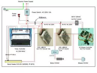
Design Overview • Basic block diagram
Thermoelectric Generation • What is a TEG? • No moving parts • Completely silent • Highly reliable
Initial TEG Housing Structure • Design parameters • 200 psi Compressive Loading • Uniform Load • Insulation
Final Structure • Fan • Water pot heatsink • Compression at the edges • Insulation at the base
Initial Converter Design • Comparison of different topologies • Flyback and Boost have high efficiencies
Flyback Advantages • Flyback Topology • Dielectric isolation • Minimal parts required • Easily derive multiple outputs
Flyback Design Issues • Low input voltage from TEG • Very high peak currents on the primary • Challenging inductor design • Availability of materials
Final Converter Design • Boost topology • Main components • Inductor • MOSFET • Diode • Output Capacitor
Controller • TPS 43000 • Under-voltage lockout at 1.65 V • Hiccup over-current protection • Imax(hu) = .25 / RDS(ON) = 11.36 A • Low power mode
Inductor Calculations • Minimum inductance needed to avoid operating in DCM • 5 V • Lcrit = 1.908 uH • 12 V • Lcrit = 11.27 uH Lcrit = (Rmin / 2) * Tsw(1-D)2*D
Output Filter • Moderate voltage ripple at the output • 5 V • C0 min = 3.6 uF • 12 V • C0 min = 16.8 uF Coutmin = I0max * Dmax / ( fin * vripple )
Feedback Network • Vr = [Rbias/(Rbias+R1)]* Vout • Vout = [1/(1-D)]* Vin FB pin Vr R1 Vout To PWM Comparator Rbias Vref
Testing: TEG • Approximate module Δ T • Verify power output • Verify module integrity • Calculate temperature differences across interfaces
Approximate Module ΔT • Measured temperatures • Th = 2740 C • Tc = 1250 C • Measured open circuit voltage • Voc = 1.93 V ΔT = 1100 C
Verify Power Output P0 = 4.9 Watts
Verifying Module Integrity • Voltage across .3Ω load • VR = 1.427 V • Module current • I = VR / RL = 4.76 A • Internal resistance • Ri = ( VL-Voc )/ I = .126 Ω
Calculating ΔTi • Interface temperature drop • ΔTi = (Th - Tc) – ΔT = 390 C • Values in the range of 300 C to 500 C are acceptable
Testing: Boost Converter • Vds, Vgs, output voltages and ripple voltages • Efficiencies at different loads • Testing in conjunction with the TEG • Line and load regulation
Converter Waveforms 5 V 12 V Drain Voltage Gate Voltage
5 V Converter Efficiency 𝜼 = 1 – Ploss/Pin
Line And Load Regulation • 5 V • % Load reg = 2.2 (.11 V) • % Line reg = 1.2 (.06 V) • 12 V • % Load reg = 5.0 (.6 V) • % Line reg = 2.2 (.264 V) % Line regulation = [Vout (highest input) – Vout (lowest input)]/ Vout nominal % Load regulation = [Vout (no load) – Vout (max load)]/ Vout nominal
Successes • Both converters worked • Good efficiencies on the converter • TEG was able to provide sufficient power
Challenges • Lead time on parts • Low input voltage controllers uncommon • Time constraints • Magnetics design can be complex
Recommendation • Importance of documentation • Maintain a well organized lab journal • Record ideas, implementation, test data, etc • Explore multiple sources • Verify design equations against different sources • Utilize design tools provided by manufacturer
Potential Improvements • Circuitry for low-power temperature controlled heat sink fan • Better TEG structure • Compression/Thermal expansion • Uniform Load • Smaller and lighter design • Safety
Acknowledgments • Professor Paul S. Carney • Professor Patrick L. Chapman • Professor Philip T. Krein • Paul Rancuret • ECE machine shop • Scott McDonald • David Switzer • Greg Bennett • ECE parts shop • Mark Smart • Power Lab • Andy Friedl • Kevin Colravy • Ben Niemoeller
Q & A QUESTIONS ?