Download
1 / 52
520 likes | 540 Vues
Design and build a USB interface adaptor for FPGA-eb1 to demonstrate its power and usefulness with components like GPS and LCD display. The project schedule includes firmware, device driver, and hardware development phases. Integration plan features USB chipset and critical paths for testing. Implementation involves VHDL coding, parallel functions, and interfacing with GPS and LCD.

E N D
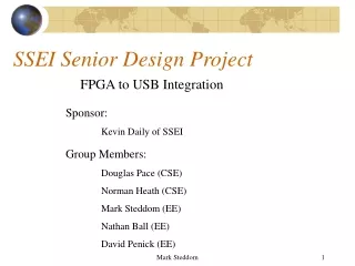
SSEI Senior Design Project FPGA to USB Integration Sponsor: Kevin Daily of SSEI Group Members: Douglas Pace (CSE) Norman Heath (CSE) Mark Steddom (EE) Nathan Ball (EE) David Penick (EE) Mark Steddom
Project Overview Design and Build a USB Interface Adaptor for the FPGA-eb1 USB P.C. Power & Ground SSEI Bus [0:7] FPGA-eb1 Mark Steddom
Project Overview Demonstrate the Power and Usefulness of the Product USB P.C. SSEI Bus [0:7] Power & Ground LCD Bus [0:10] L.C.D. FPGA-eb1 G.P.S. GPS Bus [0:2] Mark Steddom
Project Overview Demonstrate the Power and Usefulness of the Product USB P.C. SSEI Bus [0:7] Power & Ground LCD Bus [0:10] L.C.D. FPGA-eb1 Byte Blaster Parallel Interface G.P.S. GPS Bus [0:2] Mark Steddom
Project Schedule • Firmware 28 days 01/22/01 02/28/01 • Device Driver 33 days 01/22/01 03/07/01 • FPGA_EB1 Development 38 days 01/22/01 03/14/01 • USB Hardware Device 23 days 02/12/01 03/14/01 David Penick
Project Schedule cont. • Toy Development 7 days 02/12/01 02/20/01 • Application 43 days 01/15/01 03/14/01 • Integration 8 days 03/15/01 03/26/01 • Full Complete Systems Test 10 days 03/27/01 04/09/01 David Penick
Integration Plan • USB chipset • FPGA code • FPGA to USB • GPS • LCD display David Penick
Firmware LCD Application Device Driver GPS VHDL Hardware Integration & Test Critical Path Capstone Conference David Penick
Critical Path cont. • Firmware 2/28/01 • Device Driver 3/7/01 • Tested with USB Interconnect • Hardware 3/14/01 • USB interconnect David Penick
Critical Path cont. • VHDL 3/14/01 • FPGA_eb1 connected to USB interconnect • Toy 2/20/01 • GPS 2/20/01 • LCD 2/15/01 • Application 3/14/01 • Map Display 3/2/01 • NMEA Decoder 2/2/01 • USB Driver Interface 2/27/01 David Penick
Device Driver Application Port USB Host Controller Demonstration Devices GPS USB CHIP EZ-USB fpga_eb1 Port LCD The “Toy” David Penick
Toy • Motorola GT Plus Oncore • OEM • will utilize 3 connections on the SPI connector of FPGA_eb1 • The GPS will support the NMEA (National Marine Electronics Association) protocol at 4800 baud • Motorola binary protocol at 9600 baud • Software selectable output rate (cont. or poll) David Penick
NMEA • standard protocol used by GPS receivers to transmit data • output is EIA-422A, can consider it RS-232 compatible • 4800 bps, 8 data bits, no parity and one stop bit (8N1) • sentences are all ASCII David Penick
NMEA cont. • Each sentence begins with a dollar sign ($) and ends with a carriage return linefeed • Data is comma delimited • All commas must be included as they act as markers • Some GPS do not send some of the fields David Penick
Toy cont. • LCD Display • will utilize 11 connections on the fpga_eb1 board • The LCD screen will be black pixels on white background • It will have a resolution of 640 by 480 pixels • It allows for independent pixel drawing David Penick
Toy cont. • Display data transferred in the form of two 4-bit parallel data through shift registers • When the data of one line (640 pixels) has been inputted, it will be held automatically by the built-in LCD driver. David Penick
Device Driver Application Port USB Host Controller Demonstration Devices GPS USB CHIP EZ-USB fpga_eb1 Port LCD FPGA and VHDL Nathan Ball
VHDL • Max Plus II Baseline • Graphical Editor • Text Editor (VHDL) • Floor-plan Editor • Wave-form Editor • Simulator Nathan Ball
VHDL • Implements functions on an FPGA • Makes use of subroutines • Makes use of previously defined functions • Extensive libraries • Parallel functionality Nathan Ball
Graphical Implementation Nathan Ball
VHDL CODE --vhdl code for AND2 gate library IEEE; use IEEE.STD_LOGIC_1164.all; entity AND2 is port ( Input_1, Input_2: in STD_LOGIC; Output_1 : out STD_LOGIC; ); end AND2; architecture V1 of AND2 is begin Output_1 <= (Input_1 and Input_2); end V1; Nathan Ball
Requirements • USB Interface –8 I/O lines • GPS –Serial Data: 2 lines • LCD –Parallel Data: 2 lines • 4 lines Unused • Toy Interface • Out to GPS: 3 Lines - 2 Data, 1 GND • Out to LCD: 11 Lines - 2 CLK, 8 Data, 1 GND Nathan Ball
Structure FPGA USB Interface Pipe Data GPS Unit LCD Display Parallelize Data Nathan Ball
Paralellizing the Data • First Bit placed in lowest order bit of upper register • Second Bit placed in lowest order bit of lower register • 1 Data Line In => 8 Data Lines Out • Sent in on a Clock Signal • Sent out with 2 Clock Signals Nathan Ball
Device Driver Application Port USB Host Controller Demonstration Devices GPS USB CHIP EZ-USB Port fpga_eb1 LCD The USB Interface Mark Steddom
USB Interface Adaptor AN21XX Mark Steddom
USB Interface Adaptor USB-B AN21XX Mark Steddom
USB Interface Adaptor USB-B MAX882 AN21XX Mark Steddom
USB Interface Adaptor USB-B MAX882 AN21XX 24LC00 Mark Steddom
USB Interface Adaptor USB-B MAX882 AN21XX SN75240 24LC00 Mark Steddom
Device Driver Application USB Host Controller Port Demonstration Devices GPS USB CHIP EZ-USB Port fpga_eb1 LCD Firmware and Device Driver Douglas Pace
Firmware and Driver Requirements • Must be compliant with the USB 1.1 Specification Document. • Allow for bi-directional communication between a host computer and the fpga_eb1. Douglas Pace
New Non-functional Requirements • Should be easy for the end user to develop applications and lab experiments. • Provide the most versatile interface as possible. Douglas Pace
Must allow for bi-directional support between any application and the fpga_eb1. Must be easy to design applications and VHDL for the fpga_eb1. Should have the ability to utilize as many or as few of the I/O pins on the EZ-USB chipset as needed. Firmware and Device Driver Douglas Pace
USB Basics • USB Communication all occurs between endpoints. • These endpoints are device defined. The EZ-USB supports up to endpoint 15. • There are 4 types of transfer types: • ISO • Bulk • Interrupt • Control Douglas Pace
USB Transfer Types • ISO or isochronous transfers • Data integrity not guaranteed. • Data speed is always guaranteed. • Packet sizes of up to 1023 bytes during each frame. • Bulk transfers • Data speed is not guaranteed. • Utilizes all integrity checks available. • Packet sizes are limited to 8,16,32,64 bytes. Douglas Pace
Driver->Firmware Protocols • Utilize 5 endpoints other than the system defined endpoint 0. • Endpoint 1 will be a bulk configuration endpoint. • Endpoint 2 & 3 are bulk endpoints. 2 will be input, 3 output. • Endpoint 8 & 9 will be ISO endpoints. 8 will be input, 9 output. Douglas Pace
Packet Identifier 1 byte I/O Pin Number 1 byte Input / Output 1 byte Serial (0) or Parallel (1) 1 byte Extra Info: Interrupt line to link for Parallel or timer length for Serial 4 bytes Firmware Protocol Cont. • Endpoint 1 will accept 8 byte long packets. Douglas Pace
I/O Line 1 byte Number of Bytes 1 byte Data 62 bytes Firmware Protocol Cont. • Endpoints 2,3,8,9 will utilize 64 byte packets. Douglas Pace
Firmware->FPGA Protocol • As we have already seen, the firmware will allow both serial and parallel data loads to the fpga. • This will be done using strictly timed data reads or dumps, or using an external interrupt line as the clock for parallel data. • This will allow a versatile system that allows for multiple styles of data transfer. Douglas Pace
Driver • Driver will attempt to maintain data integrity by only allowing a single application access to the USB device at a time. • Driver will format packets using specific functions, allowing simple and rapid application development. Douglas Pace
Device Driver Application Port USB Host Controller Demonstration Devices GPS USB CHIP EZ-USB fpga_eb1 Port LCD The Application Norman Heath
Application Requirements • It must communicate with the fpga via the USB driver and interconnect. • It will display a topographical map and relevant information from the GPS unit. Norman Heath
Design Methodology • We are using an incremental model approach in the design and implementation of the application. • We will add features to the application during the rest of design and implementation. Norman Heath
Why use an Incremental approach • A thorough set of requirements was never specified for the application. • This will allow us to have a functioning program for the rest of the project. • We can show what we have to anyone and they can make suggestions at anytime. • It almost guarantees a functioning application when the project is over. Norman Heath
Application Design The design of the application centers around the follow: • It will gather information from a GPS unit through the USB driver and device interconnect. • It will display this information to the user by using a topographical map and textual/graphical feedback. Norman Heath
Application Design One of its capabilites is: • It allows the user to import a compressed or uncompressed .bmp file representing a map. It then allows the user to configure a settings file for that map. These settings are persistent (they remain after the application is terminated). Norman Heath
Configuring a map Norman Heath
Application Design Other capabilities • At any time it allows users to display any maps they have previously loaded and setup. • As GPS location coordinates transition off a map, it will prompt the user to select another map that has coordinates that are in range of the current latitude and longitude. Norman Heath