
CDMA Technology Overview
E N D
Presentation Transcript
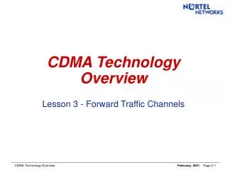
CDMA Technology Overview Lesson 2 – Spectrum Usage and System Capacity
Spectrum Usage and System Capacity:Signal Bandwidth, Vulnerability and Frequency Reuse AMPS, D-AMPS, N-AMPS 2 1 3 1 Users 3 7 1 6 4 5 Vulnerability: C/I @ 17 dB 30 30 10 kHz Typical Frequency Reuse N=7 GSM 2 Vulnerability: C/I @12-14 dB 1 8 Users 3 4 200 kHz Typical Frequency Reuse N=4 1 CDMA Vulnerability: Eb/No@6 dB 1 1 1 1 1 17 dB = 101.7@ 50 1 1 22 Users 1 1 14 dB = 101.4@ 25 1 1 1 12 dB = 101.2@ 16 1 1250 kHz Typical Frequency Reuse N=1 • Each wireless technology (AMPS, NAMPS, D-AMPS, GSM, CDMA) uses a specific modulation type with its own unique signal characteristics • The total traffic capacity of a wireless system is determined largely by radio signal characteristics and RF design • RF signal vulnerability to Interference dictates how much interference can be tolerated, and therefore how far apart same-frequency cells must be spaced • For a specific S/N level, the Signal Bandwidth determines how many RF signals will “fit” in the operator’s licensed spectrum
Relationship Between Eb/N0 and S/N Signal Power Bit Rate S R Noise Power Bandwidth N W S R Eb N0 S R W N S N W R = X X N W E / t B / t Eb = N0 = = = = Signal to Noise = = Processing Gain W 1,250,000 10 2.11 8 Kb vocoder (Full Rate) = = 130 = = 21.1 dB R 9,600 W 1,250,000 10 1.94 13 Kb vocoder (Full Rate) = = 87 = = 19.4 dB R 14,400
S/N Advantage of CDMA Signal to Noise Processing Gain (W/R) Eb N0 100.6 Þ S N S N 101.94 100.6 10-1.34 X = = = = -13.4 dB 101.94 Tech-nology Modulation Type Channel Bandwidth Quality Indicator S/N AMPS Analog FM 30 KHz. C/I @17 dB S/N @17 dB N-AMPS Analog FM 10 KHz. C/I @17 dB S/N @17 dB D-AMPS DQPSK 30 KHz. C/I @17 dB S/N @17 dB GSM GMSK 200 KHz. C/I @12-14 dB S/N @12 to 14 dB CDMA QPSK/OQPSK 1,250 KHz. Eb/No @6dB S/N @–13.4 dB 17 dB = 101.7@ 50 1 -13.4 dB = 10-1.34@ 0.046 = 14 dB = 101.4@ 25 22 12 dB = 101.2@ 16
Overlaying CDMA on an AMPS System 1.77 MHz Power 260 KHz 1.25 MHz Nominal Bandwidth 260 KHz GUARD BAND GUARD BAND CDMA CARRIER Frequency Each CDMA Channel: 1.250 MHz ÷ 30 kHz = 41.7 = ~41 AMPS channels Each Guard Band: 260 kHz ÷ 30 kHz = 8.7 = ~9 AMPS channels TOTAL: 1.77 MHz ÷ 30 kHz = 59 AMPS channels AVAILABLE AVAILABLE 41 AMPS channels 41 AMPS channels 41 AMPS channels CDMA CDMA CDMA CDMA CDMA 41 AMPS channels 9 AMPS channels Minimum Separation between AMPS/TDMA and CDMA center frequency: (1,250 kHz ÷ 2) + 260 kHz = 885 kHz 885 KHz
CDMA 800 MHz Cellular Spectrum Usage Channel Numbers 1 1 991 333 334 666 667 716 717 799 991 333 334 666 667 716 717 799 1023 1023 A” A” A B A’ B’ other uses A B A’ B’ 1 10 10 1.5 2.5 1 10 10 1.5 2.5 824 MHz 849 MHz 869 MHz 894 MHz Reverse link (i.e., mobile transmits) Forward link (i.e., cell site transmits) Possible CDMA Center Freq. Assignments ~300 kHz. “guard bands” possibly required if adjacent-frequency signals are non-CDMA (AMPS, TDMA, ESMR, etc.) • All CDMA RF carriers are 1.25 MHz. wide • can serve ~22 users w/8 kb vocoder (~17 users w/13 kb vocoder) • The cellular spectrum of one operator is 12.5 MHz. wide. You’d expect that 10 CDMA carriers would fit. However, only 9 carriers can be used • operators must maintain a “token” AMPS presence for several years • “guard bands” are required at the edges of frequency blocks or any frequency boundaries between CDMA/non-CDMA signals • no guard bands are required between adjacent CDMA carriers
CDMA PCS 1900 MHz Spectrum Usage Guard Bands Paired Bands Licensed Licensed Channel Numbers Unlicensed 1199 1199 299 300 400 699 700 800 900 299 300 400 699 700 800 900 0 0 B B B B B B Data Voice MTA MTA BTA MTA MTA BTA T T T T T T A A A A A A A D B E F C A D B E F C 15 5 15 5 5 15 10 10 15 5 15 5 5 15 1910 1930 1990 1850 MHz MHz MHz MHz Reverse link (i.e., mobile transmits) Forward link (i.e., cell site transmits) • A, B, and C licenses can accommodate 11 CDMA RF channels in their 30 MHz of spectrum • D, E, and F licenses can accommodate 3 CDMA RF channels in their 10 MHz of spectrum • 260 kHz guard bands are required on the edges of the PCS spectrum to ensure no interference occurs with other applications just outside the spectrum
Overlaying CDMA on the 1900 MHz Band 1.77 MHz Power 260 KHz 1.25 MHz Nominal Bandwidth 260 KHz CDMA CARRIER GUARD BAND GUARD BAND Frequency Each CDMA Channel: 1.250 MHz ÷ 50 kHz = 25 channels Each Guard Band: 260 kHz ÷ 50 kHz = 5.2 = ~5 channels TOTAL: 1.77 MHz ÷ 50 kHz = 35.4 = ~ 35 channels Just as with the CDMA on AMPS overlay, a GUARD ZONE is also needed
Number of Voice Channels (As AMPS Channels Are Converted to Digital) 8 kbps CDMA 200 150 13 kbps CDMA 100 Number of Voice Channels 50 0 TDMA AMPS Number of CDMA Carriers 0 1 2 3 4 5 6 7 8 9
CDMA Frequency Channel Assignment at 800 MHz Cellular 1023 991 333 334 666 667 715 716 799 1 A” A Band B Band A’ B’ Channel Numbers 1013 31 73 115 157 199 241 283 384 426 468 510 552 594 636 691 777 8 7 6 5 4 3 2 1 1 2 3 4 5 6 7 9 9 8 * ** * *Requires frequency coordination with non-cellular interferers **Requires frequency coordination with A-band carrier CDMA A-Band Carriers CDMA B-Band Carriers A Band Primary Channel 283 A Band Secondary Channel 691 B Band Primary Channel 384 B Band Secondary Channel 777 • IS-95 RECOMMENDS TO START CDMA DEPLOYMENT • WITH EITHER THE PRIMARY OR THE SECONDARY CHANNEL
CDMA Frequency Clearing: A-band(N=7 Reuse Pattern) N = 7 a b g • To deploy a CDMA carrier centered on AMPS/TDMA Channel 283, AMPS/TDMA Channels 254 through 312, inclusive, must be cleared from the CDMA coverage area • The CDMA channel is implemented, centered on AMPS/TDMA Channel 283. The first usable AMPS/TDMA Channels (outside of the Guard Zone) are Channels 253 and 313
CDMA Frequency Clearing: B-band(N=7 Reuse Pattern) N = 7 a b g • To deploy a CDMA carrier centered on AMPS/TDMA Channel 384, AMPS/TDMA Channels 355 through 413, inclusive, must be cleared from the CDMA coverage area • The CDMA channel is implemented, centered on AMPS/TDMA Channel 384. The first usable AMPS/TDMA Channels (outside of the Guard Zone) are Channels 354 and 414
Overlay Guard Zone Deployment The Guard Zones are needed between CDMA and other systems because CDMA increases the noise floor for those systems AMPS Only Cells approx 19 channels per sector AMPS Only Cells (GUARD ZONE) approx 16 channels per cell CDMA & AMPS Cells approx 16 channels per sector one CDMA channel/carrier/frequency ( 42 + 9 + 9 ) ÷ 21 = 2.8 = ~3 AMPS channels must be cleared per sector in the CDMA & AMPS area and in the Guard Zone to make room for the first CDMA channel/carrier/frequency
Other Technologies: Avoiding Interference AMPS-TDMA-GSM 1 1 4 7 2 6 7 3 5 6 1 4 5 1 2 4 1 7 2 3 6 3 5 1 1 • In conventional radio technologies, the desired signal must be strong enough to override any interference • AMPS, TDMA and GSM depend on physical distance separation to keep interference at low levels • Co-channel users are kept at a safe distance by careful frequency planning • Nearby users and cells must use different frequencies to avoid interference Figure of Merit: C/I (carrier/interference ratio) AMPS: +17 dB TDMA: +14 to 17 dB GSM: +12 to 14 dB
Other Technologies: Avoiding Interference AMPS-TDMA-GSM 1 1 4 7 2 6 7 3 5 6 1 4 5 1 2 4 1 7 2 3 6 3 5 1 1 • In conventional radio technologies, the desired signal must be strong enough to override any interference • AMPS, TDMA and GSM depend on physical distance separation to keep interference at low levels • Co-channel users are kept at a safe distance by careful frequency planning • Nearby users and cells must use different frequencies to avoid interference Figure of Merit: C/I (carrier/interference ratio) AMPS: +17 dB TDMA: +14 to 17 dB GSM: +12 to 14 dB
CDMA: Using a New Dimension • All CDMA users occupy the same frequency at the same time! Frequency and time are not used as discriminators • CDMA operates by using CODES to discriminate between users • CDMA interference comes mainly from nearby users • Each user is a small voice in a roaring crowd -- but with a uniquely recoverable code • Transmit power on all users must be tightly controlled so their signals reach the base station at the same signal level Figure of Merit: Ec/Io, Eb/No (energy per chip [bit] /interference [noise] spectral density) CDMA: Ec/Io -17 to -2 dB CDMA: Eb/No ~+6 dB
The Network View MTX BSC BTS WalshCodeWt I PN+Dt SIother users 9600 bps4800 bps2400 bps1200 bps 19200 sps9600 sps4800 sps2400 sps T-1 64 kbsPCM 1.2288 Mcps T-1 Unch. 19.2 Ksps BCN BCN BCN IF DataScrambling RF RF Switching Voice Coding Packet Routing CDSU CDSU Packet Routing ConvolutionalEncoderR=1/2 K=9 Symbol Repetition BlockInterleaver MUX Up-Conversion HPA IF Modulation 19.2 Ksps 19.2 Ksps 1.2288 Mcps 800 Hz User Address Mask (ESN) Long Code PNGenerator Decimator¸64 Decimator¸64 Q PN +Dt SQother users BTU/STU Combiner Correlator T-1 64 kbsPCM Power ControlDecision 1.2288 Mcps T-1 Unch. Correlator BCN BCN IF RF De-modulation LNA Down Correlator Voice Coding Switching Packet Routing CDSU CDSU Packet Routing Viterbi Decoder BlockDe-Interleaver Conversion Correlator PN +Dt
The Handset View Antenna symbols Receiver Traffic Correlator S chips PN Generator Walsh Generator RF IF IF voice bits Mixer RF Duplexer & Bandpass Filters IF BPF Traffic Correlator Viterbi Decoder Vocoder LNA IF PN Generator Walsh Generator audio Power Amplifier message bits Traffic Correlator LO PN Generator Walsh Generator RF Mixer Local Oscillator (Synthesized) Search Correlator (Pilots) LO CPU & Control Algorithms PN Generator Walsh=0 Open Loop Pwr Control IF IF IF Transmit Gain Adjust: Closed Loop Pwr Control IF Modulator message bits LONG CODE Generator audio Baseband Filtering Quadrature Spreading Direct Seq. Spreading Data Burst Randomizer Orthogonal Modulator Block Interleaver Conv. Encoder & Symbol Rep. Vocoder chips symbols symbols voice bits Transmitter
Lesson Review • What is the C/I ratio (in decibels) for GSM users? 12 – 14 dB • Processing Gain (W/R) is • the rate of bit rate to bandwidth • the rate of bandwidth to bit rate • all of the above • none of the above The rate of bandwidth to bit rate • Frame Error Rate (FER) is a better performance measurement that Bit Error Rate (BER)? True
Lesson Review, continued • All CDMA RF carriers • are 1.25 MHz wide • can serve ~ 22 users with a 8kb vocoder • can serve ~ 17 users with a 13kb vocoder • all of the above • none of the above all of the above • As the number of voice channels increase, the number of AMPS carriers decrease. True • Long Code PN generation occurs in the • MTX • BSC • BTS • none of the above BTS