Inductance and Magnetic Fields
Chapter 14. Inductance and Magnetic Fields. Introduction Electromagnetism Reluctance Inductance Self-inductance Inductors Inductors in Series and Parallel Voltage and Current Sinusoidal Voltages and Currents Energy Storage in an Inductor Mutual Inductance Transformers Circuit Symbols

Inductance and Magnetic Fields
E N D
Presentation Transcript
Chapter 14 Inductance and Magnetic Fields • Introduction • Electromagnetism • Reluctance • Inductance • Self-inductance • Inductors • Inductors in Series and Parallel • Voltage and Current • Sinusoidal Voltages and Currents • Energy Storage in an Inductor • Mutual Inductance • Transformers • Circuit Symbols • The Use of Inductance in Sensors
14.1 Introduction • Earlier we noted that capacitors store energy by producing an electric field within a piece of dielectric material • Inductors also store energy, in this case it is stored within a magnetic field • In order to understand inductors, and related components such as transformers, we need first to look at electromagnetism
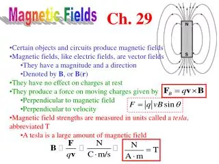
14.2 Electromagnetism • A wire carrying a current I causes a magnetomotive force (m.m.f) F • this produces a magnetic field • F has units of Amperes • for a single wire F is equal to I
The magnitude of the field is defined by the magnetic field strength,H , where where l is the length of the magnetic circuit • Example – see Example 14.1 from course text A straight wire carries a current of 5 A. What is the magnetic field strength H at a distance of 100mm from the wire? Magnetic circuit is circular. r = 100mm, so path = 2r = 0.628m
The magnetic field produces a magnetic flux, • flux has units of weber (Wb) • Strength of the flux at a particular location is measured in term of the magnetic flux density, B • flux density has units of tesla (T) (equivalent to 1 Wb/m2) • Flux density at a point is determined by the field strength and the material present or where is the permeability of the material, r is the relative permeability and 0 is the permeability of free space
Adding a ferromagnetic ring around a wire will increase the flux by several orders of magnitude • since rfor ferromagnetic materials is 1000 or more
When a current-carryingwire is formed into a coilthe magnetic field isconcentrated • For a coil of N turns them.m.f. (F) is given by and the field strength is
The magnetic flux produced is determined by the permeability of the material present • a ferromagnetic material will increase the flux density
14.3 Reluctance • In a resistive circuit, the resistance is a measure of how the circuit opposes the flow of electricity • In a magnetic circuit, the reluctance,S is a measure of how the circuit opposes the flow of magnetic flux • In a resistive circuit R = V/I • In a magnetic circuit • the units of reluctance are amperes per weber (A/ Wb)
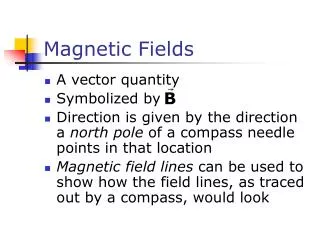
14.4 Inductance • A changing magnetic flux induces an e.m.f. in any conductor within it • Faraday’s law: The magnitude of the e.m.f. induced in a circuit is proportional to the rate of change of magnetic flux linking the circuit • Lenz’s law: The direction of the e.m.f. is such that it tends to produce a current that opposes the change of flux responsible for inducing the e.m.f.
When a circuit forms a single loop, the e.m.f. induced is given by the rate of change of the flux • When a circuit contains many loops the resulting e.m.f. is the sum of those produced by each loop • Therefore, if a coil contains N loops, the induced voltage V is given by where d/dt is the rate of change of flux in Wb/s • This property, whereby an e.m.f. is induced as a result of changes in magnetic flux, is known as inductance
14.5 Self-inductance • A changing current in a wire causes a changing magnetic field about it • A changing magnetic field induces an e.m.f. in conductors within that field • Therefore when the current in a coil changes, it induces an e.m.f. in the coil • This process is known as self-inductance where L is the inductance of the coil (unit is the Henry)
14.6 Inductors • The inductance of a coil depends on its dimensions and the materials around which it is formed
The inductance is greatly increased through the use of a ferromagnetic core, for example
Equivalent circuit of an inductor • All real circuits also possess stray capacitance
14.7 Inductors in Series and Parallel • When several inductors are connected together their effective inductance can be calculated in the same way as for resistors – provided that they are not linked magnetically • Inductors in Series
14.8 Voltage and Current • Consider the circuit shown here • inductor is initially un-energised • current through it will be zero • switch is closed at t = 0 • I is initially zero • hence VR is initially 0 • hence VL is initially V • as the inductor is energised: • I increases • VR increases • hence VL decreases • we have exponential behaviour
Time constant • we noted earlier that in a capacitor-resistor circuit the time required to charge to a particular voltage is determined by the time constantCR • in this inductor-resistor circuit the time taken for the current to rise to a certain value is determined by L/R • this value is again the time constant (greek tau) • See Computer Simulation Exercises 14.1 and 14.2 in the course text
14.9 Sinusoidal Voltages and Currents • Consider the application of asinusoidal current to an inductor • from above V = L dI/dt • voltage is directly proportional tothe differential of the current • the differential of a sine wave isa cosine wave • the voltage is phase-shifted by90 with respect to the current • the phase-shift is in the opposite direction to that in a capacitor
14.10 Energy Storage in an Inductor • Can be calculated in a similar manner to the energy stored in a capacitor • In a small amount of time dt the energy added to the magnetic field is the product of the instantaneous voltage, the instantaneous current and the time • Thus, when the current is increased from zero to I
14.11 Mutual Inductance • When two coils are linked magnetically then a changing current in one will produce a changing magnetic field which will induce a voltage in the other – this is mutual inductance • When a current I1 in one circuit, induces a voltage V2 in another circuit, then where M is the mutual inductance between the circuits. The unit of mutual inductance is the Henry (as for self-inductance)
The coupling between the coils can be increased by wrapping the two coils around a core • the fraction of the magnetic field that is coupled is referred to as the coupling coefficient
Coupling is particularly important in transformers • the arrangements below give a coupling coefficient that is very close to 1
14.12 Transformers • Most transformers approximate to ideal components • that is, they have a coupling coefficient 1 • for such a device, when unloaded, their behaviour is determined by the turns ratio • for alternating voltages
When used with a resistive load, current flows in the secondary • this current itself produces a magnetic flux which opposes that produced by the primary • thus, current in the secondary reduces the output voltage • for an ideal transformer
14.13 Circuit Symbols
14.14 The Use of Inductance in Sensors • Numerous examples: • Inductive proximitysensors • basically a coilwrapped around a ferromagnetic rod • a ferromagnetic plate coming close to the coil changes its inductance allowing it to be sensed • can be used as a linear sensor or as a binary switch
Linear variable differential transformers (LVDTs) • see course text for details of operation of this device
Key Points • Inductors store energy within a magnetic field • A wire carrying a current creates a magnetic field • A changing magnetic field induces an electrical voltage in any conductor within the field • The induced voltage is proportional to the rate of change of the current • Inductors can be made by coiling wire in air, but greater inductance is produced if ferromagnetic materials are used • The energy stored in an inductor is equal to ½LI2 • When a transformer is used with alternating signals, the voltage gain is equal to the turns ratio