The Background of Nominal Unit shear strength(V s ) for shear wall in US standard
170 likes | 556 Vues
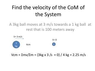
The Background of Nominal Unit shear strength(V s ) for shear wall in US standard. L i Rui & Zhao Jianchi. Content. Introduction Specimen Test setup Test Procedure Calculation Reference. Introduction. 1 plf (pound per linear foot) → 14.59 N/m.

The Background of Nominal Unit shear strength(V s ) for shear wall in US standard
E N D
Presentation Transcript
TheBackground of Nominal Unit shear strength(Vs) for shear wall in US standard Li Rui & Zhao Jianchi
Content Introduction Specimen Test setup Test Procedure Calculation Reference
Introduction 1 plf(pound per linear foot)→14.59 N/m Vs :Tabulated Nominal Unit Shear strength Determine allowable unit shear strength Use in Allowable Stress Design method(ASD) and Load Resistance Factor Design method(LRFD)
Introduction • ASTM E2126- Cyclic Load Test for Shear Resistance of Vertical Element of the lateral Force Resisting System for Buildings Vs • ASTM E564- Static Load Test for Shear Resistance of Framed Walls for Building(basic test for ASTM 2126) First Major Event (FME) Ultimate displacement (Δm) ASTM-American Society for Testing and Materials
Introduction Example: Typical8-ft(2.4-mm) wall wood-framed walls with wood structural panel sheathing-Aspect ratio (h/b) of 2:1 or less. FME=0.8 in.(20mm); aspect ratio of 4:1, FME= 1.2 in(31mm) Wood-framed walls with gypsum sheathing-Aspect ratio of 2:1 or less, FME=0.25 in(6.4mm) First Major Event (FME) The FEM is the first significant limit state that occurs during the test. The limit state is an event demarks the two behavior states, at which time some structural behavior of the specimen is altered significantly. FME is determine by conducting monotonic load test.
Specimens-ASTM E2126 Frame Panel sheathing Tested Shear wall Diagonal bracing Bracing element fastening Type Spacing edge distance of fasteners Connection Spacing of the shear connections and hold-down connectors Sheathing Panel Attachments Attachment to the Test base
Test setup Optional horiz. joint Hold-down Anchors (ASTME2126) (枠組壁工法耐力壁及びその倍率性能試験・評価業務方法書 日本建築総合試験所)
Test setup If necessary both Japan and US use the tie-rod method
Test procedure-loading method Consists of two pattern. The first pattern consists of three phase, at displacements representing 25%, 50%, 75% of anticipated FME. Method-A SPD method (Sequential-phased Displacement Procedure)
Test procedure-loading method Each phase of the second pattern contains one initial cycle, three decay cycles, and a number of stabilization cycles. For nailed wood frame walls, three stabilization cycles is enough. The amplitude of each decay cycle decreases by 25% of initial displacement. Method-A SPD method (Sequential-phased Displacement Procedure)
Test procedure-loading method ISO Displacement Schedule includes 2 patterns The first displacement pattern consists of five single fully reversed cycles at displacements of 1.25 %, 2.5 %, 5 %, 7.5 %, and 10 % of the ultimate displacement ∆ m . The second displacement pattern consists of phases, each containing three fully reversed cycles of equal amplitude, at displacements of 20 %, 40 %, 60 %, 80 %,100 %, and 120 % of the ultimate displacement ∆m Method-B ISO method
Test procedure-loading method CUREE involves displacement cycles grouped in phases at increasing displacement levels. Starts with a series of initiation cycles at small, equal amplitudes. Then, each phase of the loading consists of a primary cycle with amplitude expressed as a fraction of the reference deformation and subsequent trailing cycles with amplitude of 75% of the primary one. Method-C CUREE method
Test procedure-loading method • Method A vs Method B • Method A maybe applicable when Fme is the yield limit state or for testing slack systems to determine a lower bound displacement causing hysteretic energy dissipation • Method B may be more applicable to systems that exhibit linear elastic behavior where FME is the strength limit state. If the ratio of Δm and FME is less than three, Method B may be preferable • Method C • Thelatestmethod。 • Formenow is a mystery
Test procedure-loading method There are two loading methods in Japanese standard. First one is used in tie-rot type. Each phase of that procedure consists of three fully reversed cycles, associating with a respective displacement level of 1/600, 1/450, 1/300, 1/200, 1/150, 1/100, 1/75, 1/50rad. When it comes to the maximum load stress , continue loading until deformation angle comes to 1/15 or load stress decrease to 80% of the max load stress. The second method is for no tie-rot type. Each phase of this method also consists of three fully reversed cycles, and associates with a respective displacement level of 1/450, 1/300, 1/200, 1/150, 1/100, 1/75, 1/50rad. When it comes to the maximum load stress , continue loading until deformation angle comes to 1/15 or load stress decrease to 80% of the max load stress.
Calculation Failure limit state----Δu(in cyclic test), Δm (in monotonic test) Strength limit state----Δpeak,PPeak Yield limit state----Δyield, Pyield
Calculation Allowable strength Pa Shear strength(Vpeak) Py 0.2Pu( Ppeak= maximum load resisted by the specimen in the given envelope, lbf(N); and L = length of specimen, ft(m) unite ----- lbf/ft or N/m Pa 2/3Pmax P1/120 or P2/150 Pmax= maximum load resisted by the specimen in the given envelope; N; and Pu=Ultimate strength, N ; and u = yield ratio calculated Du divided Dy multiplied by Pu/Py Vpeak is the tabulated design value in US standard 倍率 is the tabulated unit design value in Japanese standard
Reference • ASTM E2126-11 Standard Test Method for Cyclic (Reversed) Load Test for Shear Resistance of Vertical Elements of the Lateral Force Resisting Systems of Buildings • 木造軸組工法住宅の許容応力度設計(2008年版) • 枠組壁工法耐力壁及びその倍率性能試験・評価業務方法書