Download
1 / 47
470 likes | 604 Vues
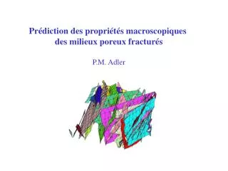
Prédiction des propriétés macroscopiques des milieux poreux fracturés P.M. Adler. Introduction. apparently solid medium. discontinuities or fractures. In most cases, the apparently solid medium is a porous medium: example of a thin section in chalk: white = solid

E N D
Prédiction des propriétés macroscopiques des milieux poreux fracturés P.M. Adler
Introduction apparently solid medium discontinuities or fractures
In most cases, the apparently solid medium is a porous medium: example of a thin section in chalk: white = solid black = holes = pores 50 mm
The discontinuities are void spaces between two rough surfaces: Two such surfaces compose a fracture Several fractures compose a fracture network: on a large scale, the fractures appear as portions of plane surfaces void space
Fundamental objective: describe and understand the transport properties of these structures with the obvious motivation that fluid will flow preferentially through the fractures Two major problems: describe the structures develop tools to study the flow precisely in these structures Practical objective: to determine upscaled properties of fractured porous media such as permeability,… from easily measurable quantities Two major problems: what are the relevant quantities to measure? how to derive the upscaled quantities of interest?
Characterization of fracture networks: from perfect knowledge to very limited informations - complete analysis:Ledésert et al (J. Volcanol. Geothermal Res., 56, 267, 1993) series of traces in nine equidistant planes of a granite block (0.5 m)3
Three dimensional sample reconstructed from the previous series of traces: Gonzales-Garcia et al, JGR, B15, 21387 (2000) approximation of the fractures by plane polygonal shapes
- traces: intersections of fractures with plane surfaces Segall and Pollard (1983) Florence lake and Ward lake
- measurement of fracture intersections with a line such as a road (or a well): measurement of dip, strike and frequency: P. Genthon et al, Geophys. J. Int., 157, 917, 2004 north 2d representation of the unit normal to the fractures south
- No information: theoretical networks: for instance isotropic population of uniformly distributed polygons inscribed in disks of a given diameter
A priori a fpm is characterized by from small to large dimensions: • fracture apertures b fracture permeability s • fractures embedded in a porous medium of permeability Km • a density r = number of fractures per unit volume • at least ! • a size distribution (radius R), a shape distribution • a distribution of orientations …. Therefore, a very complex situation with many parameters difficult to measure ! This talk is focused on the change of scales from the fracture size R up to the size of a fracture network: typically from 1 m up to 100 m in other words: how can we cope with the spatial organization of the fractures ?
Example: 2 spheres of radii R1 and R2 do not overlap if their centers is not located in the volume 4p (R1+R2)3/3 A unifying concept: the excluded volume Vex: Balberg et al (1984) the excluded volume of an object is defined as the volume into which the center of another object should not enter if overlap of the two objects is to be avoided
possible probabilistic extension to convex polygons of area Ai and perimeter Pi Vex=(A1P2+A2P1)/4 dimensionless fracture density r' = number of fractures per excluded volume = rVex/D3 = average number of intersections per fracture !
1. The percolation threshold rc • numerical results • polygons • rectangle (1/2) • . Charlaix (86) • . Garborczi (95) • Ad disk area • Ap polygon area rc Ad/Ap-1 Geometrical properties:Huseby et al, J. Phys. A, 30, 1415 (1997) - all results: r’c=2.260.04
2. Solid blocks - illustration for a 2d network: 1 2 - motivation
- number of blocks per excluded volume: - rb = number of blocks per volume D3
1 2 3. Cycles of the fracture network: - closed path along the fracture network - illustration for a 2d network
b'1 g'1 ‘ r' Numbers of cyclesper unit volume: b1 (solid lines), g1 (broken lines) Nv number of sides Nv Numbers of cycles per excluded volume b’1 (solid lines), g'1 (broken lines)
Applications to permeability: • 1. Permeability of fracture networks • Koudina et al, Phys. Rev. E, 57, 4466 (1998) impermeable matrix • inside each fracture Si , i=1,...,N: 2d Darcy law • local flow rate per unit width Ji=- sSip/m • incompressible fluid: .(sSip)=0 permeability of the fracture network: 3d unit cell submitted to a macroscopic pressure gradient < p> solve .(sSip)=0 + boundary conditions at fracture intersections: pressure and flux continuity p, J<J>= - Kn. <p>/mKn network permeability
3 steps:i. triangulation of each fracture: take into account intersections with other fractures divide the border and the intersections by a discretization length dM propagate mesh points from these points into the interior of the fracture ii. discretisation of the equations: finite volume technique iii. resolution of the discretized flow equations
broken line: Snow’s solution (1969) for random networks of infinite fractures isotropic network: Kn = 2 r’ / 3p Derivation of the network permeability Kn as a function of r': Kn Finite size effect r' - r'c Kn(r') : unique relation whatever the shape of the fractures: Kn' = 0.046 (r'- r'c) 1.57
2. Fractured porous media Physical description: . Fractures embedded in a porous solid matrix . Interaction between flow in fractures and in the porous medium . Double porosity model: Barenblatt et al (1960) . Numerical tools devised for any fracture network and any distribution of the physical properties
Single phase flow: fractures
Bogdanov et al., Water Resources Research, 39, 10.1029/2001WR000756, 2003
Meshing of the whole space by tetrahedra which locally coincide with the triangles in the fractures
Square ( ), rectangular with aspect ratios 2 ( ) and 4 ( ), Hexagonal( ) or 20-gonal ( ) fractures Results for different shapes: K'eff = K /Kms' = s /(Km R) Red lines: hexagons for increasing values of s' s' Notice the role of r' again! These curves provide master curves from which Kn can be derived when r' and s' are known
Problem: estimation of r' ? let us make the best use of the available data ! Data along a line or a wellbore : S. Sisavath et al, Geometry, percolation and transport properties of fracture networks derived from line data, Geophys. J. Int., 157, 917, 2004. Traces on a plane (outcrop, quarry,…): Berkowitz et Adler, Stereological analysis of fracture network structure in geological formations, J. Geophys. Res., B103, 15 339, 1998 Thovert et Adler, Trace analysis for fracture networks of any convex shape, Geophys. Res. Lett., sous presse Traces in a gallery: Gupta et Adler, Stereological analysis of fracture networks along cylindrical galleries, I. The direct problem, soumis
isotropic convex fractures: number of intersections: ni = r Vex per unit length: IL = ni/L = r A /2 in dimensionless terms: r’ = P IL Line data A, P L l
the convex fracture (of area Af and normal nf) intersects theprofile (of length L and parallel to p) when its center belongs to thecylinder p nf L volume =L Af p.nf Line data for anisotropic distributions: number of such fractures per unit volume: rf number of intersections ni= rf L Af p.nf per unit length: rf L Af p.nf
For a family ofpolygons thrown at random, but with given orientations ni cos gij = ni.nj , Li = Sip.ni for identical shapes and sizes measured perimeter P unknown
crudeapplication of the method: 90 fractures with a total surface of 2.6 m2 R = 0.085 m evaluation of <nI> : two axes on three planes: 66 intersections over a total length of 2.61 m
r’ = <nI> P = 13.5 percolation formula: K’ = 0.046 (r’ - r’c)1.57 = 2.03 Snow formula: K’ = 2 r’ / 3p = 2.9 permeabilities: - calculated on the real network along the 3 directions of space with impermeable lateral boundaries: Kxx = 0.66 Kyy =1.89 Kzz=2 excellent agreement between the various evaluations !
Plane data: • intersection of fractures with a plane: outcrop, quarry,… • derivation of relations independent of the shape of the fractures when they are convex for: St surface density of traces <c> average trace length St surface density of intersections between traces quantities functions of r, <P> and <A> Thovert and Adler, Geophys. Res. Lett., in press relations valid for polydisperse networks as well!
anisotropic case: relations which can be used in two ways i. derivation of self consistency relations obtained by elimination of r, <P> and <A> : isotropic case: k1 = k2 = k3 = 1
Another ingredient is necessary such as a shape factor: In this case, for an isotropic network: But, only r’ matters: isotropic: anisotropic ii. derivation of geometric parameters: Important: the knowledge of St, <c> and St is not sufficient to derive r, <P> and <A> !
Application to the Hornelen field of fractures: Odling, 1997 F1 F2 F3
measured quantities: • some additional characteristics: - subvertical network of square fractures - the fractures are distributed according to power laws with exponent a
calculated quantities: i. consistency: simplification of the traces into three family of given orientation: only k1 can be used ii. determination of r’: isotropic 1.03 anisotropic 0.82
Calculation of K: Pressure (vertical axis) as a function of the point location (x,y): color = flux intensity
Numerical calculations: Kxx / s = 0.473 ; Kyy / s = 0.254 Analytical calculations: Snow formula: K’ = KR/s = 2 r’ / 3p K/s = 2 r’ / (3p R) R is derived from <c>: <c> = p <A> / <P> = pL / 4 L side of a square circumscribed in a circle of radius R = 2-1/2L Result: K / s = 0.2 !
Data along a gallery: EDZ Forpro • direct problem analyzed for a population of isotropic disks
gallery projection of the disk onto the XY-plane full intersection The various possibilities: partial intersection with one or two traces
Examples of trace maps for various radius distributions:
derivation of various types of quantities: i. probability of intersections: possible distinction between partial and full intersections excellent analytical approximation ii. trace lengths: numerical analysis only
Mean trace <c> for a population of randomly oriented monodisperse disks as a function of rd = Rdisk/Rg disk plane intersection disk-gallery intersection
present conclusions: - rd < 0.5 : equivalence with disk-plane intersection • - little influence of the distribution of the disk radii • on the characteristics of the trace lengths! Next: Inverse analysis of real data in the framework of Forpro: Mont Terri, Tournemire, Bure,…
Conclusion: An integrated approach for the evaluation of macroscopic properties of fractured porous media with many developments : 1. geometrical analysis including polydisperse systems 2. development of codes in order to analyse new phenomena: multiphase flows, well tests, solid mechanics, hydromechanical properties, wave propagation, …. Merci de votre attention !