Download
1 / 26
260 likes | 420 Vues
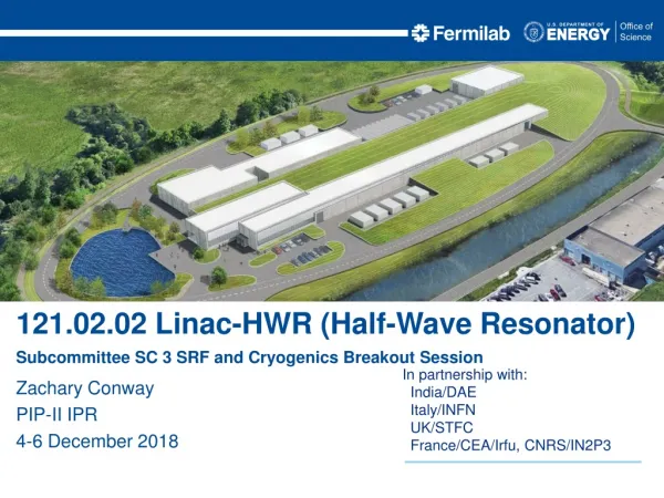
121.02.02 Linac-HWR (Half-Wave Resonator) Subcommittee SC 3 SRF and Cryogenics Breakout Session. Zachary Conway PIP-II IPR 4-6 December 2018. Outline. Scope/Deliverables Requirements Interfaces Design Maturity Technical Progress to Date ESH&Q Risks and Mitigations Summary.

E N D
121.02.02 Linac-HWR (Half-Wave Resonator) Subcommittee SC 3 SRF and Cryogenics Breakout Session Zachary Conway PIP-II IPR 4-6 December 2018
Outline • Scope/Deliverables • Requirements • Interfaces • Design Maturity • Technical Progress to Date • ESH&Q • Risks and Mitigations • Summary
Argonne National Laboratory - Accelerator Development Group: • Designing, building and commissioning superconducting accelerators since 1977. • All retired group members still work 1+ days per week. • My relevant experience: • Superconducting resonators spanning ion/electron velocities from 0.05•c to 1.0•c. • All superconducting device ancillary hardware. • 6 different types of superconducting resonator cryomodules operating at 2.0 or 4.5 K. • Superconducting accelerator commissioning. • Project Manager (L3) for HWR Cryomodule
Project Organization • Cryomodule and subcomponents designed by FNAL and ANL. • ANL is fabricating and assembling the half-wave resonator (HWR) cryomodule. • At ANL: • Accelerator Development Group Leader = Mike Kelly. • ANL HWR Cyromodule Manager = Zack Conway. • FNAL: • L2 SRF/Cryo: Genfa Wu • CAM/L3 Manager: Joe Ozelis • Project Engineer: Allan Rowe
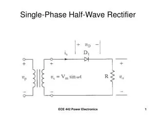
Scope and DeliverablesWBS 121.02.02 Linac – HWR System Req. Charge #2 Beam-Line-Flange to Beam-Line-Flange Length • ANL is responsible for design, procurement, sub-component testing, assembly of HWR CM, and final room temperature leak checking. • The HWR cryomodule will operate continuous wave with a beam current of 2 mA to accelerate the beam from 2.1 – 10.3 MeV.
WBS 121.02.02 L3 System Requirements Charge #2 • Cavity performance: • 2 MV per cavity, @ Pcavity < 2 W in offline testing. • Solenoid operation: • 6 T solenoids. • Power couplers: • Offline testing demonstrating 7 kW forward power on resonance. Check off resonance conditions. • Cryogenic loads: • Delivery in Q3FY19, no contingency.
Interfaces Charge #2 • The HWR Cryomodule must successfully interface with a number of other systems within the PIP-II Accelerator Complex. • These interfaces take the form of: • Mechanical • Electrical • RF (HP & LL) • Controls & Software • Cryogenic systems • Safety systems • Accelerator Physics (Requirements) • In addition, there is an Organizational Interface between ANL & FNAL, that actively jointly manages the HWR CM project. • Daily contact (phone/email) • Weekly (or more often) visits to ANL site • This will expand to multiple days/week, and include additional FNAL staff assisting with CM assembly • Bi-Weekly Management meeting
Interfaces Charge #2 • Interfaces agreed upon and defined in April 2014. • Interfaces are documented in TC ED0007564 • Technical Specification for Interfaces • Interface Control Document • Minor revisions ongoing • Communicated via L3 to affected WBSs • Physical Interface Boundary corresponds to the physical envelope of the HWR CM • Functional Interface Boundary is defined via FRS.
HWR Cryomodule Design History Charge #2 • Design/safety reviews for the HWRs and cryomodule were held at Argonne (ANL) with FNAL and ANL subject matter experts performing the reviews: • HWR review 5/17/2012, and • cryomodule review 5/16/2013. • All design reviews were conducted in compliance with ANL’s procedures, LMS-PROC-305. • Procurement readiness reviews were carried out at ANL per ANL controls. HWR Cryomodule Mock Assembly
HWR Cryomodule Design Charge #2 Conduction Cooled Leads (FNAL) Sub-Atmospheric HTXG Output Helium Relief Port Helium Manifold Cooldown Manifold Slow Tuner Gas Heat Exchanger Ti Strong-Back Half-Wave Resonator SC Solenoid Vacuum Manifold 2.2 m X 2.2 m X 6.2 m (overall) 18,650 pounds
Progress to date – Past activities Charge #1 • Design finished • All HWR cavities qualified • All HWR cavities/couplers/tuners qualified as a system • All solenoids tested, including one cavity/solenoid test • CM mock assembly performed including LN2 cooldown and alignment verification • Work Control Documents in place with final document pending ANL ESHQ approval. • New clean room for string (“clean”) assembly has been qualified • Baseline schedule developed, adopted, and being used to track progress • HWR schedule (zero internal float) reviewed on 30 August 2018. • Shipping company engaged with FNAL/ANL to develop and evaluate shipping plan, preliminary Transport Readiness Review held, 14 August 2018
Progress to date – Current activities Charge #1 • Presently we are cleaning components for final assembly. • Solenoid cleaning = finished. • Cavity cleaning next. • Cavity vacuum manifold, beam-line gate valves and clean instrumentation last. • Next steps: clean assembly → final assembly → Transportation LCLS-II-HE Cavity HWR Solenoid
Cryomodule Progress Charge #1 HWR Cryomodule Mock Assembly
Cryomodule Testing Charge #1 Alignment Measurements Cryomodule Alignment Cryomodule Assembly Cool Down Data
Q Curves HWR 2.0 K Test Results Offline Testing Goal Cavity Power = 2 W • All HWR acceptance tests are finished. • Cavities are being fiducialized and cleaned for final assembly now.
Half-Wave Resonator Microphonics & RF Power Charge #1 Measured HWR1 Microphonic Frequency Detuning • All HWR tested have a df/dP ~ 11 Hz/mbar. • With a helium pressure stability of 0.1 mbar → Df = 1.1 Hz. srms = 2.5 Hz HWR Cavity Power Time (Seconds) Mechanical Vibration Frequency (Hz)
Half-Wave Resonator w/ Coupler Offline Testing Charge #1 • All 8 cavity/coupler pairs are tested and meet acceptance criteria: 7 kW, on resonance, off resonance by ±90 degrees • All hardware now being prepared for clean assembly 6 5 4 2,3 1
Half-Wave Resonator w/ Solenoid Offline Testing Charge #1 • To decrease the accelerator lattice length we have integrated x-y steering coils into the focusing solenoid package. • Important design issue: • Minimize stray field @ the RF cavity to prevent performance degradation due to trapped magnetic flux. HWR with Solenoid • Measured RF surface resistance with a sensitivity of ±0.1 nOhm before and after each quench of the cavity. • The cavity was quenched with the solenoid and the steering coils energized. • No quantifiable change to the cavity RF surface resistance. Cavity quenched x10 at this field level.
Half-Wave Resonator & Slow Tuner Offline Testing Charge #1 HWR with Slow Tuner • The HWR cryomodule will use pneumatic slow tuners → pneumatic slow tuners have been in operation at Argonne on superconducting cavities since the 1970s. • Slow tuners are installed on all HWRs during offline testing. • Slow tuners are actuated through their full range to verify response. • 162.5 MHz ± 60 kHz is exceeded for all HWRs. • The tuner resolution is < 0.1 Hz, our measurement limit. • Slow tuners are operating as planned and testing has demonstrated this.
ESH Charge #6 • Safety is our highest priority. • Work at Argonne is done in compliance with ANL ES&H. • Providing a working piece of hardware goes hand-in-hand with work planning and control at ANL. • ESH requirements and protocols governing the FNAL and ANL collaboration on SRF are documented in the FNAL/ANL MOU on SRF Cavity Surface Processing, signed 4/21/2006 with addendum added on 8/15/2014. • Hazards addressed at ANL include: • Chemical safety, • Cryogenic safety, • Pressure systems safety, • Radiation safety, and • Cryomodule component testing and assembly work control documents.
ESH Charge #6 • Designs and Engineering Calculations have been reviewed by ANL ESH staff and relevant committees to ensure compliance. • FNAL is beginning review of ANL documentation in preparation for FNAL ORC process • Engineering notes (cavity, vacuum vessel, etc.) • Piping Engineering notes • FMEA (to be completed) • What-If analysis (to be completed)
Quality Management Charge #6 • HWR CM QA strategy includes the following • Design and production/procurement reviews • Development, review, and approval of FRS, TRS, and Interface documents • Critical vendor evaluation and oversight • Process/procedure review • Training • HWR CM QC strategy includes the following • Inspection of parts, components, to ensure conformance with requirements • Component and sub-components testing/qualification • Work Control Documents, FNAL documentation of work performed • Use of FNAL Vector system to track non-conformances, dispositions, corrective actions • Vendor QA/QC compliance monitoring • Comprehensive CM testing at PIP2IT prior to CD-3
Quality Management Charge #6 • Work quality will be quantified in the PIP-II Injector test (PIP2IT). • Testing all major components prior to cryomodule final assembly. • ANL: Cavities, couplers, solenoids, etc • FNAL: BPMs, magnet conduction cooled leads, sub-atmospheric heat exchanger • 1 optional cavity/coupler test with spares is pending. Does not affect schedule.
Risk Management Charge #2,7 • HWR WBS responsible for one Project Risk: • RT-121-02-008 - HWR Cryomodule does not meet technical performance requirements • This risk is mitigated/retired upon successful testing of the HWR cryomodule in the PIP2IT Test Facility (4QFY19, 1QFY20) • Cryomodule performance demonstrated under operational conditions (2K, all 8 cavities & solenoids powered simultaneously, full LLRF control) • This risk has no technical impact on other CM designs • This risk is retired before CD-3 • Risk probability is reduced via component and subsystem testing prior to full assembly (QA/QC program).
Risk Management Charge #2,7 • Risk mitigation prior to PIP2IT testing: • HWR cavity performance • Each HWR cavity is tested offline to determine RF performance and intrinsic cryogenic load • Power coupler performance • Every HWR/coupler pair is tested offline prior to installation in the cryomodule. • Solenoid operation • First article tested at vendor (Cryomagnetics) and ANL. • Following 7 units tested at Cryomagnetics. • BPMs tested at FNAL • CM Assembly Dry Run validates assembly & alignment strategy • Frequent contact between ANL & FNAL teams.
Summary • Design developed by collaboration between FNAL and ANL • HWR Cryomodule FRS created and approved in 2014. • Design reviews conducted in 2012 and 2013: • FNAL experts sat on panels. • Found the HWR design addressed the PIP-II injector requirements • Risks are mitigated by sub-component testing and testing in PIP2IT • ESH and QA plans are in place and being followed • Plan on delivering cryomodule to FNAL in Q3FY19. • Thank you for your attention We are on track for CD-2/3a and look forward to your feedback