Download
1 / 15
160 likes | 298 Vues
Helium Vessel Design, Study Video Conference 28 June, 2013 . HIE-ISOLDE SC Solenoids. Thermocontraction unbalance, maxima Requested opertional conditions Vessel Condition Diagram Simulations of the cases in AutoDesk Inventor Vessel Condition Diagram with simulation results

E N D
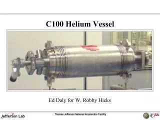
Helium Vessel Design, Study Video Conference 28 June, 2013 HIE-ISOLDE SC Solenoids
Thermocontraction unbalance, maxima • Requestedopertionalconditions • Vessel Condition Diagram • Simulations of the cases in AutoDesk Inventor • Vessel Condition Diagram with simulation results • Cycling and steady stress • Summary • Contents
Precondition: The whole structure is stress free at room temperature • Thermocontraction Unbalance • Yoke + ends length is rigid • Bellows in beam pipe will be designed to have adequate stroke • Flexzones in ends will take up difference between cover and yoke+ends Lengths: Yoke 344 mm Cover 362 mm Beam pipe 406 mm 1 mm Yoke Worst case differences [mm] (Lyoke+ends – Lpipe/cover) 3 mm Beam pipe Threadconnection Cover cases
Vessel test at room temperature and 6.5 bar @ CERN: • Cool down (1.3 bar, max 1.1 mm) • Heat up (1.3 bar, max -0.75 mm) • Operation (1.3 bar, 0.35 mm) • Quench during operation (4.5 bar, coil <100 K) • Loss of vacuum, possibly followed by quench (4.5 bar, max -0.75 mm) @ Danfysik: • No conditions exceed the limits given above • Safety valves (lift disks, redundant) designed to Plift< 4.5 bar • Cool down LN2, then LHe • Heat up, either with He gas into vessel only or combined with low He pressure in cryostat • Requestedoperationalconditions
Pressure [bar] 6.5 • Vessel Condition Diagram Vessel test Loss of vacuum 4.5 Quench Normal operation Heat up Cool down 1.3 -0.75 0.35 1.1 represents worst case/extreme condition, input to Inventordesign -> determination of maximum stress in these cases Lyoke+ends- Louter vessel [mm] Additional simulation of the normal operation case
Vessel pressure test: • Room temperature and 6.5 bar. • Vessel cover is fixed in mid plane and vessel hub is fixed at threaded surface.
Cool down: Yoke is warm and vessel is cold. • ½ vessel cover crimp displacement = 0.55mm.Vessel end hub is fixed. Force (6.5 kN) is added on vessel cover (Z direction) until displacement is 0.55 mm.1.3 bar inside pressure.
Heat up: Yoke is cold and vessel is warm. • ½ vessel cover expand displacement = 0.4 mm. Vessel cover is fixed in mid plane. Force (5.3 kN) is added on vessel hub (Z direction) until displacement is 0.4 mm.1.3 bar inside pressure.
Normal operation conditions: • ½ Vessel cover is crimped 0.2 mm compared to yoke.Vessel end hub is fixed. Force (4.3 kN) is added on vessel cover (Z direction) until displacement is 0.2 mm.1.3 bar inside pressure.
Quench during operation: Coil <100 K. • ½ vessel cover is crimped 0.2 mm related to yoke.Vessel end hub is fixed. Force (11.8 kN) is added on vessel cover (Z direction) until displacement is 0.2 mm.4.5 bar inside pressure.
Loss of vacuum, possibly followed by quench: • ½ vessel cover expand displacement = 0.38 mm. Vessel cover is fixated in mid plane. Force (11.75 kN) is added on vessel hub (Z direction) until displacement is 0.38 mm.4.5 bar inside pressure.
Pressure [bar] • Vessel Condition Diagram • with Simulation Results 141 MPa 6.5 Maximum stresses Vessel test Loss of vacuum 105 MPa 168 MPa 4.5 Quench Normal operation Heat up Cool down 135 MPa 118 MPa 1.3 53 MPa -0.75 0.35 1.1 316L 0.2 % elastic limit typical 220-240 MPa (BSSA.org.uk) Lyoke+ends- Louter vessel [mm]
Cyclic loading -> fatigue: • Low-cycle fatigue range (< 1E4 cycles), fatigue failure does not occur when below elastic limit (general, conservative) • Endurance limit/fatigue limit of 316L is 270 MPa, failure does not occur until after 1E6-1E7 cycles (British Stainless Steel Association) • Smooth surface finish enhances endurance • Stress at operational conditions -> creep • Observation: generally a phenomena studied above 500°C • Thermally activated, depends exponentially on temperature • Cycling and steady stresses
52% of σfatigue >10E6 cycles • Vessel test at room temperature and 6.5 bar @ CERN: • Cool down (1.3 bar, max 1.1 mm) • Heat up (1.3 bar, max -0.75 mm) • Operation (1.3 bar, 0.35 mm) • Quench during operation (4.5 bar, coil <100 K) • Loss of vacuum, possiblyfollowed by quench(4.5 bar, max -0.75 mm) @ Danfysik: • No conditions exceed the limits given above • Safety valves (lift disks, redundant) designed to Plift< 4.5 bar • Cool down LN2, then LHe • Heat up, either with He gas into vessel only or combined with low He pressure in cryostat • Summary I 50% of σfatigue >10E6 cycles 50% of σfatigue >10E6 cycles 20% of σfatigue >10E6 cycles 39% of σfatigue >10E6 cycles 62% of σfatigue >10E6 cycles 62% of σfatigue >10E6 cycles
Danfysik propose to move the design to FDR stage 2 • Detailled engineering and manufacturingdrawings • Instrumentation diagram • Summary II