Well Design Principles for Efficient Water Extraction
Learn about designing different types of wells such as tube wells and open wells for optimal discharge and recharge of aquifers. Understand the construction and intricacies of well screens for effective groundwater extraction.

Well Design Principles for Efficient Water Extraction
E N D
Presentation Transcript
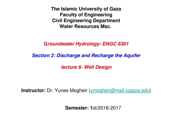
The Islamic University of GazaFaculty of EngineeringCivil Engineering DepartmentWater Resources Msc. Groundwater Hydrology- ENGC 6301Section 2: Discharge and Recharge the Aquiferlecture 6- Well Design Instructor: Dr. Yunes Mogheir (ymogheir@mail.iugaza.edu)Semester: 1st/2016-2017
Wells Water well: is a hole usually vertical excavated in the earth for brining groundwater to the surface : • It classified into : • Open wells • Tube wells • For open well (figure 16.36) • Have bigger diameter • Low discharge • Less than 20 m depth • Shallow or deep wells (figure 16.37) • The shallow wells is liable to be contaminated by rain water mixed with minerals or organic matter from decomposing animals and plants
Tube Wells • Is a long pipe or tube is bored or drilled deep into the ground intercepting one or more water bearing stratum. • Larger discharge can be obtained by getting a larger velocity and larger cross sectional area Deep wells: • The depth ranges between 70 to 300 m • The general average standard discharge in the tube well is in the order of 40 to 45 liter/sec • The diameter of the hole is 0.6m up to 60 m and 0.56 m below 60 m • Are drilled by heavy duty rotary drilling rigs or Percussion drilling rigs in a hard boulder areas
Tube Wells Shallow wells: • The depth ranges between 20 to 70m • Drill one aquifer and may yield as high as 15-20 liter/sec Tube wells in Hard Rocky soil • Very difficult to be constructed • The hole diameter holes of 10 to 15 cm • The depth up to 300 m or more • Drilled using down the hole hammer rig (DTH rigs)
Types of Tube Wells cavity Tube wells (Figure 16.40): • Draws water from the bottom of the well and not from the sides • The flow is spherical and not radial • Very economical where plain well pipe is lowered into the required depth in the aquifer • The cavity wells need to be developed carefully and slowly using a centrifugal pump • The well is discharged with low rate until the water become clear • The process repeated till the normal draw down and clear discharge is obtained
Types of Tube Wells Screen type wells (Figure 16.43): • Screen pipes or slotted pipe ( pipe strainers) are located opposite the water bearing formation • After placing the slotted pipe in the bore hole, a mixture of gravel is pured into the bore hole between the wellpipe assembly and the casing pipe • In fine aquifers the effective grain size (D10) may be less 0.25 mm and the uniformity coefficient Cu may be 2.0 or less
Design of well screen Screen type wells (Figure 16.43): • The design of the screen is largely influenced by the characteristics of the water bearing formation • Dry sieve analyses of the aquifer sample obtained during drilling of the bore hole (grain size distribution curve) • From the curve the following should be determined • Effective size (D10) : sieve size through which 10% of the particle shall pass • uniformity coefficient Cu is the ratio of the sieve size passing 60% of the aquifer to the sieve size passing 10% (In a uniform material Cu is equal to or less than 2)
Design of well screen Design the size of the slot openings of a screen • The slot openings depends on the size of the aquifer material • Oversized slot will pump finer material and will be difficult to obtain clear water • Undersized slot will result in more head loss and corrosion • The optimum value is determined by matching the size of the opening and the grain size distribution curve • In Practice it ranges between 0.2 mm to 5 mm
Design of well screen Slot opening for anon gravel pack well • The optimum slot size is chosen as the one which retain 40% of the sand. • This may vary from aquifer to another Slot opening for a gravel pack well • On the grain size distribution curve a point of 90% size is retained indicate the optimum slot size. • The actual size may be fixed within 80% of the D10 size of the gravel pack
Design of well screen Gravel Pack design • The gravel pack should be design before the design of the size of the slots • The gravel pack should be designed using Pack Aquifer Ratio (PA) PA ratio = D50 of the gravel / D50 of the aquifer • PA ration should be between 9 to as 12.5 fro Cu ≤ 2 • PA ration should be between 12 to as 15.5 fro Cu ≥ 2 However Cu should be kept is equal or less than 2.5
Design of well screen Gravel Pack design • The thickness should be normally be fixed in the rage of 7.5 cm to 20 cm. • Thicker gravel pack dose not increase the well yield • The important is the ratio of the grain size of the gravel pack and of that of the aquifer • See example 16.13
Design of well screen Design of the length and the size of the screen • The total length is controlled by thickness of the aquifer • The screen length will be less if the area of its openng is more and vice-versa • The area of the screen opining per m length of the screen is between 15 to 20 % of the screen area • the diameter of the screen is selected to satisfy the optimum safe entrance velocity of the aquifer which is related to K as shown in table 16.5 • K varies between 0.05 to 0.1 cm/s and then ve varies between 2 to 3 cm/s
Design of well screen Design of the length and the size of the screen • The controlling factor for designing the diameter is ve where is calculated by dividing the discharge per m length of the screen by the total area of the opining per unit length. • The diameter can be selected based on the optimum value of ve • Table 16.6 shows the recommended value of screen diameter
Design of well screen Design of the length and the size of the screen • The minimum length of the screen can be design as h= Q /( A0 . ve) Q = design discharge of the well A0 = the area of screen opining per m length of the screen ve =is the optimum entrance velocity for the K value of the aquifer and mean K value of aquifer and the gravel pack The screen is usually located in the center of the aquifer • The minimum length should be adjusted by about 75 to 90% of the confined aquifer. • In unconfined aquifer 1/3 to ½ of the bottom depth is screened.
Design of well screen Type of well screen PVC screen covered with a stainless steel net. This product is particularly suited for fine sand and silt as it does not clog and can be installed to greater depths due to its high collapse resistance.
Design of well screen Type of well screen PVC pipes and screens are available from 33mm diameter to 630mm diameter
Design of well screen Type of well screen Stainless Steel Water Well Screen
Construction and Boring of Tube well The methods of boring wells can be classified into • Driven wells • Jetted tube wells • drilled tube wells Driven Well (Figure 6.51) where the assembly is forced down the ground to penetrate into the water bearing formation Jetted Well (Figure 6.52) A hole in the ground is made by the cutting action of a stream of water which is pumped into the well through a small pipe diameter.
Construction and Boring of Tube well The methods of boring wells can be classified into Drilled Well • Cable tool method of drilling (figure 16.53) is known as percussion drilling ( hammering and cutting) which suitable for cutting consolidated rock 2. Direct Rotary method (figure 16.54) • It is suitable for unconsolidated formation such as sand, gravel • The method involves a continuously rotating hollow bit through which a mixture of clay and water or mud is forced. • The bid cuttings are carried up in the hole by rising the mud
Well Development The stabilization of the walls of a well adjacent to the screen, by a process which remove the fine particles from the formation immediately surrounding the well screen, leaving coarser particles to contact and surround the screen. This is done by overpumping or rewhiding the well ( starting and stopping the pumping)
Kiwi's (V6) 6" Borehole submersible pumps suitable for 6" or larger boreholes. Superior hydraulic design of impeller and diffuser make these pumps are most efficient. Utilization of top class material allow pumps to be reliable, long lasting and increases ites wear resistance towards sand. State of the art manufacturing process ensures optimum and consistent quality of these pump. Manufactured from corrosion & abrasion resistant materials. Close coupled to a submersible electric motor. Designed for flow rate upto 1400 LPM and head upto 430 meter.
Sandy aquifer of thickness 15 m K= 0.9 m/day Impermeable layer of thickness 4 m Kurkar aquifer of thickness 25 m K= 1.5 m/day Impermeable layer of thickness 6m Exercise 3 Make the design of a well by considering the following characteristics of the aquifer and the discharge value is 75 m3/hr. the water level in the unconfined aquifer is 5 m below the surface. Assume any missing information.