The Intermediate Guide to best rv solar battery charger
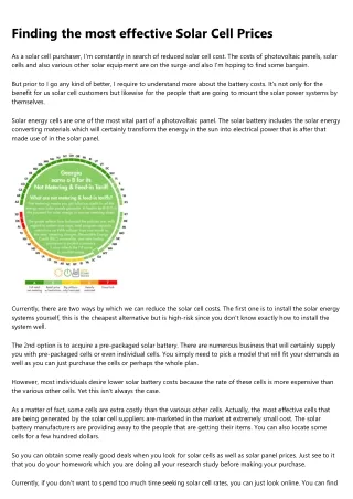
<h1>Just how Do I Locate the Right Solar Cell Rate?</h1> <p>When you make a decision to develop a solar power system to power your home, the initial point you will require is a solar cell. It will certainly likewise be required to save the power you create to be utilized the next day. As you can visualize, the more batteries you have the greater the price to build a solar power system.</p> <p> </p> <p>There are many makers of solar batteries, each one asserting to have the most effective battery offered. You will certainly likewise require to buy the solar batteries and also cables. The very best place to seek a good producer of these parts is the net. There are lots of reliable business online that offer these elements at practical costs.</p> <p> </p> <p>When you construct a solar energy system to run your house, you will need the solar battery and also all of the elements it requires. The type of battery you select will depend on the amount of power you intend to produce. It will likewise rely on the size of your photovoltaic panel. The solar cells that you acquire will identify how much power your battery will create.</p> <p> </p> <p>The dimension of your solar power system will additionally affect the cost to build your solar power system. If your system is large, the price to develop it will certainly be a lot more pricey than a smaller sized system. You can build a tiny planetary system and afterwards add even more later on. The cost to construct your solar power system will likewise be impacted by the quantity of job you have to perform in order to place it together.</p> <p> </p> <p>Producers of solar panels do not charge much for the components, yet do bill for labor. The more labor you need to do the much less the parts will cost. When you develop a solar energy system, you can get a total set which contains every one of the components you require to build a solar power system. If you do not have the time or knowledge to do all of the job on your own, you may wish to purchase a kit that only includes the parts you need to develop your solar energy system.</p> <p> </p> <p>It will cost you a little a lot more to acquire a kit than it will to purchase solar batteries and solar batteries independently. Sets are likewise a lot more budget friendly than building your own solar energy system from square one. Kits include everything that is necessary to develop your solar energy system. Kits are easy to install and also they will certainly conserve you cash when you need to change the batteries, solar batteries and wires.</p> <p> </p> <p>The amount of time and also cash you will certainly spend building your solar energy system will certainly affect the solar battery cost as well. If you want to save money on the battery, you will wish to make your solar power system as reliable as feasible. The more solar cells, wires, and batteries you need to develop your solar power system the extra pricey it will certainly be.</p> <p> </p> <p>You can discover the components for your solar energy system in several places, however you will need to choose the price to build your solar energy system prior to you go shopping. There are several reputable suppliers online that can offer every one of the parts you will require to build your solar power system.</p> <p> </p> <p>When acquiring the solar panels, you ought to just buy from a company that supplies a money back assurance. Lot of times business will sell the batteries at a really small cost but they will not supply a warranty that the batteries will certainly last. You can find a premium quality brand name of battery at a discount rate price, yet you can still get a premium quality battery at a discount price if you know where to look.</p> <p> </p> <p>When you have figured out the quantity of money that you wish to invest in the solar energy system, you can after that identify the solar battery cost. to get the very best battery. If you are new to constructing your very own solar energy system, you might wish to go with a large size solar battery.</p> <p> </p> <p>A plus size solar energy system will give the most power you will require to run your family home appliances at home. If you are just looking for a backup system, you can utilize a small dimension solar power system. The very best dimension solar power system is established by how much electrical energy you will require to power your residence and your house home appliances.</p> <h1>Solar Panel Cost</h1> <p>If you are searching for a brand-new way to obtain power for your residence or your service, you might be interested in locating a solar cell that can save energy for your home. If you have a solar panel, a solar battery can help to keep the energy that the panels create and use that energy to power your home.</p> <p> </p> <p>This kind of system is called a solar panel. There are many different kinds of these panels and they vary in rate. The even more complicated the system the a lot more it will certainly cost to install and also the even more power it will certainly have the ability to shop.</p> <p> </p> <p>The solar battery you select is essential because it will be the thing that will certainly save every one of the energy the photovoltaic panel produces. There are several kinds of batteries readily available and the one you select will certainly depend on the power you need, the dimension of your solar panel as well as how much power you will require saved in the battery.</p> <p> </p> <p>The expense of a photovoltaic panel will certainly rely on the number of panels you have, the dimension and exactly how large your solar panel is. The even more solar panels you have the more it will cost to acquire and also mount them.</p> <p> </p> <p>The dimension of the photovoltaic panel will likewise determine the price you will pay to purchase and also install the solar panel. If you have a small solar panel you will be able to purchase a less expensive system than a bigger panel.</p> <p> </p> <p>The most pricey solar panel will cost more to buy and mount than a cheaper one. You will need to determine what your power requirements are as well as how many solar panels you will need to save the power.</p> <p> </p> <p>If you currently have a photovoltaic panel you can utilize the panel's power to help shop energy that you require for your home. You will certainly have the ability to make use of the stored power to power your house as well as help to lower the price of electricity that you use.</p> <p> </p> <p>A solar cell will certainly set you back money but in the long run you will be conserving cash on your electric costs. The solar panel will certainly remain to be cheaper to buy and set up and as more panels are contributed to your solar panel the solar cell cost will go down.</p> <p> </p> <p>The larger solar panels you have will help to create even more power than the smaller ones. This energy will certainly be saved in the solar battery and will certainly assist to provide power for your house.</p> <p> </p> <p>The larger photovoltaic panels will take the sun's energy as well as convert it right into energy that your solar panel can make use of. This is why the a lot more solar panels you have the even more power you will certainly have the ability to produce as well as keep.</p> <p> </p> <p>The more photovoltaic panels you have the more solar panels you can make use of at a time. The more power you have on your panels the much more energy you will certainly have the ability to shop.</p> <p> </p> <p>The even more power you have actually saved the even more power your solar panel will certainly create. The more energy your panels can produce the much more you will be able to charge your batteries.</p> <p> </p> <p>The solar panel that you buy will certainly identify the cost of your battery. The more solar panels you purchase the more you will certainly be able to charge your batteries as well as the reduced the price of your solar battery will be.</p> <p> </p> <p>The higher the top quality of the photovoltaic panels are the more affordable the battery will be. If you have a top quality solar panel you will certainly have the ability to bill your batteries quicker as well as use less power.</p> <p> </p> <p>The lower quality solar panels will certainly not be able to bill your batteries as quick and can trigger you to utilize even more power. The reduced quality photovoltaic panels will cost even more to buy and also will need more work to be done on your photovoltaic panels to keep the battery healthy.</p> <p> </p> <p>The more solar panels that you have the even more solar panels that you will certainly need to charge your batteries. The higher the quality of the solar panel the lower the price.</p> <h1>Why is it That Your Solar Cell Cost is Extremely Reduced?</h1> <p>In this short article I will attempt to show you that there are solar battery rates which are rather low for you to own. This is due to the fact that people are starting to find out even more concerning the advantages of having a solar cell. This will certainly be particularly true if you own one of the smaller sized solar battery systems.</p> <p> </p> <p>This solar panel rate is extremely low due to the fact that you can purchase them in bulk. Simply put, if you buy one system of solar energy from a solar energy shop then you will certainly get one device of solar power from the shop. Currently if you purchase the device in bulk then you will obtain even more devices of solar energy for your requirements.</p> <p> </p> <p>This is just one of the major reasons that solar panel cost is very low. This is since you will certainly have the ability to acquire them in huge amounts as well as at reduced rates. This is specifically true if you acquire them from online solar power shops.</p> <p> </p> <p>One more factor that solar panel is so economical is due to the fact that the materials that you will certainly need for your task are so cheap. For the most part this is due to the fact that you are purchasing from an online store. So you can get all the products that you require for your project in one place.</p> <p> </p> <p>If you have a solar panel then you can utilize it in your home to power all of your home appliances. The most common usage for this is in the garage. This is because it is a really affordable solar power storage space tool.</p> <p> </p> <p>Solar power is just one of the cleanest methods to power our residences. It is additionally among the most trusted and budget-friendly ways to power our residences.</p> <p> </p> <p>If you acquire your solar power shop from a store then they can additionally give you with the solar power storage systems to help you keep solar power for future usage. This is since they will be able to help you reduced the expense of the system.</p> <p> </p> <p>When you are thinking about solar cell cost, you ought to take into consideration all of the reasons that I have just mentioned. If you acquire your solar battery from a shop after that you will certainly discover that you are conserving cash on the prices of the system as well as you will also find that the system is extremely trusted and durable.</p> <p> </p> <p>There are also many different ways that you can lower your solar panel cost. One of the primary ways that you can decrease the rate of your solar energy storage is to purchase it from an on the internet store.</p> <p> </p> <p>Because there are so many online shops that you can buy from this is one of the most effective manner ins which you can buy from one of the online stores. This way you will have the ability to buy your solar cell at a discount price.</p> <p> </p> <p>The only thing that you will have to do is to do a little bit of study by yourself and discover the most effective online shop to purchase from. In this manner you will certainly have the ability to locate the best cost for your solar panel as well as you will additionally be able to purchase from a store that is respectable.</p> <p> </p> <p>The best feature of shopping for your solar panel from an on-line store is that it is one of the easiest manner ins which you will be able to study. You can do your research online and discover the most effective rate for your solar battery.</p> <p> </p> <p>It is very important that you discover a shop that will give you a warranty that is going to last you a long period of time. You should likewise find a shop that will give you complimentary setup guidelines if you buy from them.</p> <h1>Solar Cell Price</h1> <p>If you are planning on mounting your very own solar energy system, after that among the very first things you need to comprehend is just how much a solar battery expense. There are a great deal of various solar battery systems as well as each of them includes a various rate. You need to take a while to make sure you have the best solar panel system for you.</p> <p> </p> <p>When checking out a solar battery rate, you need to remember the size of your residence. You can get batteries that are little adequate to make use of on the roofing yet after that you will certainly require to consider the size of your home. The bigger your house, the larger the battery will certainly need to be to power the whole thing. If you have a lot of sunlight, after that you will be able to purchase a very large solar panel system for your home.</p> <p> </p> <p>Some solar cells set you back much less than twenty bucks while others can cost as much as a thousand bucks. When you are acquiring the system, make certain you recognize what you are obtaining. The much better the system, the much less you will have to pay for the battery.</p> <p> </p> <p>The size of the battery is necessary due to the fact that it is mosting likely to determine how much power it can store. If you have a large battery, after that you can save even more power. A big battery can accumulate to 8 hours of electrical power, which is enough to run your whole home.</p> <p> </p> <p>Solar panel are different than photovoltaic panels. If you have a panel, then you are making use of the solar panels to accumulate the sunlight's power and also transform it to power you can make use of. Solar panels are not such as a battery system. You are only making use of the panels to gather the solar energy for a couple of hours a day and after that you need to save the energy in a battery so you can use it when it is offered.</p> <p> </p> <p>You will have to pay for your solar panel when it is set up. If you are seeking an option that is not very pricey, then you can simply utilize your existing system. If you currently have a solar panel as well as you wish to use the panels to store the power for a few days, after that you will only be spending for your battery and then you can utilize your panels throughout the day to power the lights and also devices in your house.</p> <p> </p> <p>You can utilize solar energy for a selection of various things. It can be utilized to warm your residence, warm your water and also even make use of the warm water system in your home. There are some companies that have a system that you can need to save the power in and after that you can make use of that to run devices in your home. The system can keep a great deal of energy, so you will certainly never lack power.</p> <p> </p> <p>You can additionally utilize solar power to power your automobile. There are systems that you can get that have sufficient power to obtain you your vehicle relocating with gasoline as well as you can run the lights and your warm. You will certainly conserve a lot of cash on your gas expense if you make use of solar power for all of your requirements.</p> <p> </p> <p>An additional thing to keep in mind when looking at solar energy is that you will certainly need a great deal of sunlight. If you reside in an extremely sunny location you might require to have your residence dark shielded or you might have to build some form of photovoltaic panel on the roof covering of your home to capture the sun's power.</p> <p> </p> <p>The price of a solar panel is various depending upon the dimension of the battery. A larger solar battery is going to be far more pricey than a smaller sized one. The even more power your solar panel can store the even more cash you will certainly be reducing your energy expenses. There are lots of firms that will certainly sell huge batteries at a more affordable rate to the public as well as you can utilize this money to buy a smaller battery for your home or your vehicle.</p> <p> </p> <p>If you are searching for a way to conserve cash on your utility costs, after that you may intend to check into solar energy. You will certainly save money on your regular monthly bills, conserve the atmosphere as well as aid to save the world also.</p>
86 views • 5 slides