Download
1 / 1
10 likes | 115 Vues
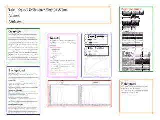
Specifications. Title: Optical Reflectance Filter for 550nm Authors: Affiliation:. Overview

E N D
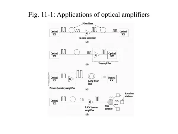
Specifications Title: Optical Reflectance Filter for 550nm Authors: Affiliation: Overview Our LaserDyne team was presented with the challenge of creating an optical band reflect filter for the United States Military. In order to achieve the project goals specified by the United States Military, the design should allow for complete reflection of light at 550nm and completely transmit light at all other wavelengths. The filter must be built using a glass substrate and layers containing either Lithium Flouride (LiF) or Zinc Sulfide (ZnS). Since complete reflectance only at 550nm is not possible in the real world, the design calls for the smallest possible bandwidth, centered at 550nm. Two major issues of the filter design are cost and reproduction ability. We discovered that as the number of layers used in the filter increased, the production cost rose dramatically and the probability of producing a defect free filter decreased. The merits of our filter include a maximum reflectance of 90.79% at 550nm and a bandwidth of approximately 87.74nm. The filter has a total of 6 layers (3 stacks) on top of the substrate. Having fewer layers was important from a cost standpoint. Our design will only cost $3,427.48 to produce per filter in bulk (100 filters per unit). The small quantity of layers also ensures trouble-free production and minimal defects. Cost Analysis • Results • The design was called for a band-reject filter of the form C[AB]ND, where A, B, C, and D can be one of two different materials, however, A and B must be different, but C and D can be the same. N represents the number of stacks. • Theoretical Calculations • Zinc Sulfate (Zns)See Figure 1 • Lithium Floride (LiF)See Figure 2 • Actual Values The actual for depth used in the design were equivalent to the values calculated in the theoretical section. The actual values for the resultant data is as follows: • β = Bandwidth = 87.74nm, and was calculated by determining the wavelength represented by ½ of the maximum reflectance. • R = Reflectivity at 550nm = 90.79% • The graphs below and the cost analysis show why using 3 stacks in significantly better than 2 stacks. Figure 1: Theoretical Calculations for ZnS Figure 2: Theoretical Calculations for LiF • Background • Importance of Project: • The design allows the user to filter/reflect green light and transmit the rest of the visible spectrum. This filter can benefit the military and other users. • The concepts on which this design was based can be modified to design a filter for any wavelength. • Previous Work: • Ideas and concepts developed to meet the required specifications in order to get the project done were discussed in the regular training session of ECEN 3613 under the supervision of Prof. C. Bunting. • Similar technology is used to create infrared vision. In this case wavelengths from the infrared portion of the electromagnetic spectrum are transmitted while all other wavelengths are reflected. • Approach and Methodology: • The first step in our design process involved researching established filter creation methods. Our research lead us to the "Handbook of Optics"[1] in which we discovered the quarter stack filter design. • Using the spectral response tool in Matlab, we tested our calculations and altered design parameters to determine our final design. • The quarter wave stack design procedure works by multiplying the quarter wave equation by any odd integer. • These conclusions are not only supported in the "Handbook of Optics"[1] but also in "Optics"[2] by Hecht. • Development of Specifications: • We evaluated our final product by comparing the center wavelength and bandwidth characteristics of our filter's response with the given specifications. We arrived at our final specifications through use of the spectral_response program in Matlab. • We based our specifications on the major design parameters we were to meet. They show that our theoretical calculations were accurate and complete. Image property of [1] References [1] Driscoll, Walter G., Handbook of Optics, New York: McGraw-Hill, Inc., 1978. pp. 8-58 to 8-75 [2] Hecht, Eugene, Optics. Third Edition. Massachusetts: Addison Wesley Longman, Inc, 1998. 2 Stacks 3 Stacks