GPS Enhanced PFD System Software Presentation
This presentation by Eric Grossmann provides a comprehensive overview of the Enhanced GPS PFD system software. It details the system specifications, including the Timeslice kernel, task modules, and CPU load calculations. Key tasks such as startup, acceleration detection, immersion detection, switch detection, GPS reception, and transmission are outlined with execution times and periodicity. The system is built on the CY8C24794 MCU, featuring 16k Flash and 1k RAM, operating at a bus frequency of 24 MHz, ensuring efficient data flow and task execution.

GPS Enhanced PFD System Software Presentation
E N D
Presentation Transcript
GPS Enhanced PFD System Software Presentation Eric Grossmann
Presentation Summary General System Specifications Timeslice Kernel Tasks Modules Data Flow Diagram Individual Task Descriptions CPU Load
General System Specifications • MCU PSOC 1 CY8C24794 • 4 Digital Blocks & 6 Analog Blocks • Bus Frequency: 24 MHz • Timeslice Kernel • Timeslice Period:100 ms • Memory Available: • 16k Flash • 1k RAM • Memory Requirement: • Less than 1k Flash • 1k RAM
Timeslice Kernel Tasks • Startup Task • Acceleration Detect Task • Immersion Detect Task • Switch Detect Task • GPS Rx Task • Tx Task
Startup Task • Initializes the system • Execution Time: • 100ms worst case. • Period: • Once at Startup
Acceleration Detect Task • Observes hex output from the sensor • Passes a hex output to the MCU. • Period 100ms • Execution Time 5μs
Immersion Detect Task • Observes changing voltage from the sensor • Converts the voltage into digital format • Passes voltage level as a hex output to the MCU. • Period 100ms • Execution Time 5μs
Switch Detect Task • Waits and recognizes a voltage level on a toggle switch. De-bounces the switch. • Period: 1s • Execution Time: 10μs
GPS Rx Task • Observes hex output from the sensor • Passes a hex output to the MCU. • Period 300s (sporadic) • Execution Time 5μs
Tx Task • Observes hex output from the MCU • Passes a hex output to the Transmitter module. • Period 300ms (sporadic) • Execution Time 5μs
CPU Load • Max CPU Load • 5us/100ms + 5us/100ms + 10us/1000ms + 5us/300000ms + 5us/300000ms = 0.01% CPU Load
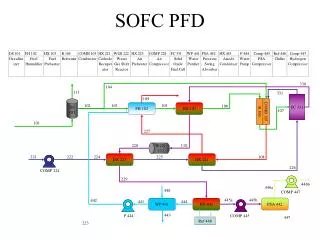
Data Flow Diagram ------------------------------------------------------------ Hardware GPSPFD.c