Composite Construction & Cambering: Technical Background & Benefits
680 likes | 746 Vues
A comprehensive presentation exploring composite steel construction, cambering, benefits of structural steel, and unique aspects of steel construction. Gain insight into composite construction methods, advantages, and disadvantages. Learn about metal decking and its importance in creating stiff and economical floor systems. Enhance your knowledge of structural steel and its impact on project management.

Composite Construction & Cambering: Technical Background & Benefits
E N D
Presentation Transcript
Composite Construction and Cambering
Introduction This presentation was developed as a teaching aid with the support of the American Institute of Steel Construction. Its objective is to provide technical background and information for composite construction and cambering. The information provided is based on common design and construction practices for structures of twelve stories or less. The Four Story Building Case study presentations document the construction of a steel frame for an office building. The case study includes photographs that were taken throughout the construction of the structural steel frame including detailing, fabrication, and erection. Project data including plans, schedules, specifications and other details are also included. The case study presentations are available in the Teaching Aids section of University Programs at http://www.aisc.org/teachingaids. This presentation goes a step further in detail in the areas of composite construction and cambering. A more in-depth background is provided and impacts of the details and design choices on schedule, cost, sequence and overall project management are addressed. The information is presented with concerns of a construction manager or general contractor in mind.
What Will You Gain From This Presentation? • General knowledge of structural steel • Knowledge of the details of composite steel construction, the components that are used, and how they are installed • An understanding of the impacts that composite steel construction may have on project schedule, cost, sequence and overall management • Insight into the process of creating camber and why cambered beams are used • Familiarity with situations where cambered beams should and should not be used, and how using cambered beams might affect a project
Benefits of Structural Steel Some benefits associated with use of structural steel for owners are: • Steel allows for reduced frame construction time and the ability to construct in all seasons • Steel makes large spans and bay sizes possible, providing more flexibility for owners • Steel is easier to modify and reinforce if architectural changes are made to a facility over its life • Steel is lightweight and can reduce foundation costs • Steel is durable, long-lasting and recyclable
Unique Aspects of Steel Construction Procurement and management of structural steel is similar to other materials, but there are some unique aspects to steel construction: • Steel is fabricated off-site (above left) • On-site erection is a rapid process (above right) • This gives use of structural steel some scheduling advantages • Coordination of all parties is essential for achieving potential advantages
Introduction to Composite Construction • Composite construction refers to two load-carrying structural members that are integrally connected and deflect as a single unit • An example of this is composite metal deck with concrete fill, steel filler beams, and girders made composite by using headed stud connectors
Introduction to Composite Construction • A steel beam which is made composite by using shear connectors, composite metal decking and concrete is much stronger and stiffer than the base beam alone • Composite floor systems are considered by many to be the highest quality type of construction • This has become a standard type of construction selected by many architects, engineers, and developers (AISC 1991)
Advantages of Composite Construction In a composite floor system the concrete acts together with the steel to create a stiffer, lighter, less expensive structure (Allen 2009)
Advantages of Composite Construction Connecting the concrete to the steel beams can have several advantages: • It is typical to have a reduced structural steel frame cost • Weight of the structural steel frame may be decreased which may reduce foundation costs • Reduced live load deflections • Shallower beams may be used which might reduce building height • Increased span lengths are possible • Stiffer floors
Disadvantages of Composite Construction • The additional subcontractor needed for shear connector installation will increase field costs • Installation of shear connectors is another operation to be included in the schedule • A concrete flatwork contractor who has experience with elevated composite slabs should be secured for the job
Metal Decking • Composite decking works together with the concrete fill to make a stiff, light-weight, economical floor system • Compare the composite decking (above left), non-composite decking (above center), and the form decking (above right) • Composite decking is available in various profiles and thicknesses
Composite Metal Decking • Decking with deformed ribs (or embossed decking), as shown, is commonly used • The deformations on the ribs allow for a stronger bond between the concrete and the decking (Allen 2009)
Composite Metal Decking Less common styles of composite decking include: • Decking with the ribs formed in a dovetail or fluted pattern (above) • Decking with welded wire fabric welded to the ribs • Decking with steel rods welded across the ribs Image courtesy of Epic Metals Corporation
Installation of Decking • Metal decking is placed on the structural steel at predetermined points in the erection sequence • Metal decking may be installed by the steel erection contractor or a separate decking contractor
Installation of Decking • Per the Occupational Safety & Health Administration Standard 1926.760(c) (2001) the decking crew may work in a controlled decking zone while placing and attaching the decking • A controlled decking zone is an area in which initial installation and placement of metal decking may take place without the use of guardrail systems, personal fall arrest systems, fall restraint systems, or safety net systems and where access to the zone is controlled
Installation of Decking • Puddle welds (above right) are commonly used to attach the decking to the structural steel below • Daily output for a four person decking crew ranges from 2700 S.F. to 3860 S.F. per day depending on the depth and gauge of the decking (Means 2014)
Installation of Decking • As an alternative to welding, powder actuated tools may be used to attach metal decking to structural steel • Powder actuated tools use the expanding gases from a powder load, or booster, to drive a fastener • A nail-like fastener is driven through the metal deck into the steel beam • The powder actuated tool, powder load, and fastener must be matched to the thickness of the structural steel beam flanges Images courtesy of Hilti Corporation
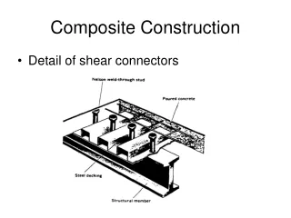
Shear Connectors • Shear connectors are commonly referred to as “studs” or “shear studs” in the trade • They are available in a range of sizes, materials, and grades • Headed studs (as shown) are most commonly used • Other, less common options for shear connectors include hooked studs or pieces of C-channel
Shear Connectors • Depending on the welding process used, the tip of the shear connector may be placed in a ceramic ferrule (arc shield) during welding to retain the weld • Shear connectors create a strong bond between the steel beam and the concrete floor slab which is poured on top of the metal decking • This bond allows the concrete slab to work with the steel beams to reduce live load deflection
Installation of Shear Connectors • Shear connectors are installed after the decking is in place • Shear connectors may be installed by the steel erection contractor or a specialty shear connector installer • The welding equipment required for installation is provided by the shear connector installer • Daily output for shear connector installation averages about 950 per day depending on the size of the connectors (Means 2014)
Installation of Shear Connectors • The bracketed numbers on the drawing above give the number of shear studs to be installed at an even spacing on the respective beam • When spacing is not uniform it will be indicated on the plan • Specified spacing of the shear connectors is an important part of the composite design and must be adhered to • Design engineers establish the shear connector spacing based on compressive and shear forces being transferred through analysis
Installation of Shear Connectors • The electrical arc process is commonly used for stud welding • An arc is drawn between the stud and the base metal • The stud is plunged into the molten steel which is contained by the ceramic ferrule • The metal solidifies and the weld is complete • The ferrules are removed before the concrete is poured (ASCE 2002, AWS 2010)
Installation of Concrete • Concrete is installed by a concrete contractor on top of the composite metal decking, shear connectors, and welded wire fabric or rebar grid (crack control reinforcing) • Pumping is a typical installation method for concrete being placed on metal decking • 140 cubic yards pumped or 95 cubic yards crane and bucket (7,500 to 15,000 sq. ft.) of elevated concrete slab may be installed per day depending on slab thickness, placement method, and crew size (Means 2014)
Installation of Concrete • There is an art to the placement of concrete on metal deck and structural steel • The work, unless shoring is used, must be executed on a deflecting surface • An experienced concrete contractor should be employed for this work • Concrete should be deposited over supporting members first, then spread toward the deck midspans • The accumulation of a deep pile of concrete must be avoided (AISC 2003, ASCE 2002)
Installation of Concrete • Concrete construction joints should be located over the beam or girder webs • Sometimes this is not possible and the joint is located near the decking midspan • Shoring should be placed beneath the construction joints until the concrete on both sides of the construction joint has reached 75% strength • This avoids a bond failure between the hardened concrete and the metal deck when the adjoining concrete is placed (ASCE 2002) • Placement of construction joints must be reviewed by the Engineer of Record
Installation of Concrete • The contractor must be aware of camber in the beams and the expected deflections • Consultation with the structural engineer may be necessary • As the concrete cures it forms a connection with the composite metal decking and shear studs • The composite floor system is now complete (AISC 2003)
Quality Control • The shear connectors used in composite construction require specific inspections and quality control • Testing procedures are specified in the contract documents or by a local building authority • AWS D1.1 – Structural Welding Code – Steel, Clause 7.8: Stud Welding (AWS 2010) specifies the tests and inspections for shear studs
Quality Control • As described in AWS D1.1 Clause 7 (AWS 2010), jobsite conditions may exist that prohibit or delay the stud welding operation • The primary issues affecting the installation of the shear connectors are: • Moisture on the decking or ferrules • Moisture between the decking and the steel beam below • A steel temperature below 0° F • In the pictures above, a torch is being used to remove snow (left) from the areas where shear studs are to be installed (right)
Quality Control • Required quality control procedures for shear connectors include pre-production tests and fabrication inspections • Pre-production testing is performed by the shear stud installer at the beginning of each work shift and includes the following steps: • Weld two sample studs • Inspect for flash • Perform bending test • Equipment settings are recorded • The stud installer performs visual fabrication inspections as studs are installed • Other testing may be specified or may be necessary if all visual inspections are not passed (AWS 2010)
Cost Impacts of Composite Construction When used appropriately, typical overall building costs will be less for composite construction than non-composite construction
Cost Impacts of Composite Construction • The U.S. national average installation cost for shear studs ranges from $2.66 to $3.83 per connector (Means 2014) • A cost comparison should be made between the reduced structural steel cost and the additional shear connector cost when determining whether or not to use composite construction
Scheduling of Composite Construction • The duration for the installation of shear studs is project dependent and should be considered on a project by project basis • Shear stud installation usually has little or no impact on the overall project schedule
Scheduling of Composite Construction • It may be possible, depending on the size of the structure and the sequencing of erection and decking, to install the shear studs as erection proceeds • It may also be possible to have a majority of the shear connectors in place and begin placing concrete for the floor slabs while structural steel is being erected in another area of the building • On the structure shown above part of the composite first floor slab was placed while erection of the structural steel for the third floor proceeded
Cambering Image courtesy of CAMBCO Inc.
Introduction to Cambering Cambering is the process of creating an intentional slight curvature in a beam Image courtesy of CAMBCO Inc.
Introduction to Cambering • Camber in a beam can be designed to compensate for either: • A certain percentage of the dead load deflection • The full dead load deflection • The full dead load deflection as well as a percentage of the live load deflection (Ricker 1989) • Camber is usually designed to compensate for deflections caused by pre-composite dead loads
Advantages of Cambering • Supporting beams will deflect under the load of concrete being placed • This deflection can be exaggerated in a composite floor system where the full strength of the system is not achieved until the concrete has cured • Cambered beams (top diagram above) should deflect to a straight line (bottom diagram above), if load and deflection are predicted accurately and camber equals deflection • This allows the floor slab to be flat while maintaining a consistent thickness (Larson and Huzzard 1990)
Advantages of Cambering • If beams are not cambered (top diagram above)the deflection under the load of the wet (plastic) concrete will result in a ponding effect in the concrete (bottom diagram above) • To create a flat floor in this situation the concrete will need to be thicker at the center of the bay where the deflection is the greatest • The volume of concrete used will typically be 10-15% more than if the floor is a constant thickness (ASCE 2002)
Disadvantages of Cambering • The use of cambered beams will, to a certain degree, be limited by other aspects of the design for a structure • Due to the complexity in detailing, fabrication, and fit-up associated with moment connections (above left), camber should not be used in moment connected beams • Beams with simple framing connections (above right) may be cambered because the end rotational resistance of a simple connection is small in comparison to that of a moment connection
Disadvantages of Cambering 1 Specified Top Of Slab Elevation 2 • The processes used to create camber in beams as well as the actual deflections under load of cambered beams are not exact • Care needs to be taken in the specification and fabrication of camber to ensure that a beam, once in place and under load, will perform within tolerances • Levelness and consistent floor thickness can be a problem (ASCE 2002) • The diagrams above show two possible results of cambered beams not deflecting as predicted under the load of the wet (plastic) concrete • Stud heads are exposed • Top of slab elevation out of tolerance
Alternatives to Cambering Alternative methods for achieving a level floor slab without using cambered beams include: • Pouring a slab of varying thickness over deflecting beams • Using over-sized beams to minimize deflection • Shore the beams before placing the concrete (Larson and Huzzard 1990) 2 1 3 Shoring Concrete At 75% Strength
Shoring • Shoring may be used in lieu of cambering • The construction documents must specify the use of shoring • There are several advantages to using shoring: • Lighter floor beams may be used • Cambers do not need to be designed or fabricated • Less beam deflection allows for better control of the slab thickness • Shoring can accommodate a contractor’s special loading requirements
When to Camber • Filler Beams • Composite Floor Beams • Girder Beams • Members with uniform cross section (Ricker 1989)
When Not to Camber • Braced Beams (above right) • Spandrel Beams (above right) • Cantilevered Beams (above left) • Crane Beams • Moment Connected Beams (Ricker 1989)
When Not to Camber • Beams under 20 feet in length (above right) • Beams with end plate connections • Beams with moment connections (above left) • Beams with non-symmetrical loading (Ricker 1989)
Heat Cambering Heated Areas Beam Top Side of Beam When Installed Support • Beams may be cambered by applying heat to small wedge-shaped areas at specific increments along the beam (Ricker 1989) • The beam is place upside down on supports so the “bottom” flange can be heated • The heated flange expands under the heat and contracts as it cools • Camber is induced in the opposite side of the beam as the heated flange cools • Advancing this slide will begin an animation which shows the expansion and contraction that occurs in a heat cambered beam The animation will repeat after several seconds
Installation of Heat Cambered Beams • A heat cambered beam should be erected with the heat marks on the bottom side of the beam (see top diagram above) • This places the beam in a camber up (or concave down) orientation • Heat marks can be seen on the beams in the bottom picture above
Cold Cambering • Cold cambering methods are more widely used and generally more economical than heat cambering • The beam is mounted in a frame and force from a ram(s) is used to bend the beam to create camber (Ricker 1989) Image courtesy of CAMBCO Inc.
Creating Camber Image courtesy of CAMBCO Inc. • Cambering is most commonly done at the fabricator’s shop after the connections are fabricated (AISC 2010) • The fabricator may mark cambered beams to ensure proper installation