Download
1 / 17
170 likes | 339 Vues
Virtual Accelerator plan and status at RCS. Web page of my work: http://nacci.tokai.jaeri.go.jp/~harada/index.html. Hiroshima University, Graduate School of Science Experimental Quark Physics Lab ( & JAEA Accelerator Development Group ) Hiroyuki Harada

E N D
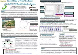
Virtual Accelerator plan and status at RCS Web page of my work: http://nacci.tokai.jaeri.go.jp/~harada/index.html Hiroshima University, Graduate School of Science Experimental Quark Physics Lab (& JAEA Accelerator Development Group) Hiroyuki Harada MR/RCS beam commissioning meeting in KEK Oct. 25th (Tues), 2005
Plan for virtual accelerator 1. Estimation of the best K value of each magnet from matching by simulation code 2. Estimation of the measurement method of each parameter and the beam & elements condition from the monitor's signal by the tracking. → Reflection to real measurement. 3. Estimation of the beam loss by MARS .
Operation panel with GUI Control Model by VA Start virtual operation The signal of each monitor Set Magnets the signal of each monitor Operating Log DB Operating parameter DB1(DB for elements) IOC Interface Power Source Physics value⇔Device value Transformation parameters Position information of the elements EPICS Channel name EPICS IOC PCAS SimulationInput File Simulator SAD SIMPSONS STRUCT/MARS ・・・ Element Real Accelerator Virtual Accelerator
Plan 1 ~ operation and matching • Matching will be carried out by SAD, but maybe switch to JAD in the future. • Operation panel with GUI for commissioning will be created by JAD (script by java based SAD) until the comprehensive examination of RCS around Dec. 2006. • The GUI operation panels for each operating mode and scenario will be created. • This will carry out COD correction and search of the best K1 tune by tune, etc.
Plan 2 ~ examination of measurement method of each parameter by VA • The measurement of the tune (now in progress) • The measurement of the chromaticity (now in progress) • The measurement of the dispersion function • The measurement of the Beta function • The measurement of all other parameters
Plan 3 ~ estimation of beam loss • The estimation of the beam loss will be calculated by MARS, using the results from the tracking by Simpsons. • The other thing than those above is unknown yet.
Status for VA • VA system via EPICS PCAS • - Preliminary system was created. • System to create the input files for simulation code from DB • - Trace3D, SAD, MAD and XAL only QM and BM was created by Sako-san. • Examination of measurement method for each parameter • - Measurement for tune and chromaticity is now in progress. • Integration of simulation codes (SAD, Simpsons and MARS) • - The communication between EPICS and Simpsons is now in progress.
The construction of system~ The control system of simulation code via EPICS PCAS GUI Operation panel (by KBFrame) Monitor signal K1 value EPICSPCAS Monitor signal K1 value Simulator EPICS : Experimental Physics and Industrial Control System PCAS : Portable Channel Access Server Figure. A created the sample operation panel with GUI
Side band by Synchrotron Oscillation Measurement of the tune • For the beam condition, εx, y : 216 pi mmmrad Number of particles : 4800 Spread of the dp/p : 1% Length of the bunch : about 83 m Non space charge Non fluctuation of the BPMs
RCS L (m) 0.81 p (GeV/c) 0.61 → 3.82 Z (Ω) 100 P (W) 1000 d (m) 0.509 The exciter at RCS The exciter gives the beam the kick with Δx’ at a point in RCS ring turns by turns. θrms is the kick-angle by the exciter, p is the beam momentum, β is Lorenz beta, c is the speed of light, P is the power supplied from the amp, d is the length of electrode plate, Ex is the electric field. The frequency spectrum of the exciter is the band-limited white noise of the frequency width with ΔΩ, Ωj is the frequency, φj is the random initial phase, N is the number of the spectrum that the amplitude is constant. Table.The parameters of RCS-Exciter Figure.The white noise of simulated RCS-Exciter
Measurements of the Chromaticity RF frequency Δf vs dp/p The right figure shows that a change of the RF frequency makes the dp/p of the beam a fluctuation. The chromaticity is gotten by the measurement of Δν for each dp/p (or the RF frequency). Chromaticity :ξ = Δν/ Δp/p task It seems that the RF in SAD is not right when the RF frequency is changed. So, the RF is under examination. If the RF has a buggy behavior, I will simulate the RF by using the other code.
The time schedule of VA at RCS Start to create the scenario for the commissioning at RCS The communication between EPICS and Simpsons will be done. The main code of the tracking replace SAD to Simpsons. Start of the beam commissioning at RCS Submission of my thesis 2006 2007 now the comprehensive examination at RCS Start to create the operation panel with GUI by JAD The coordination of the connection between EPICS and the operation panel with GUI by JAD the completion of the operation panel with GUI by JAD