P3K Stimulus Design Update
P3K Stimulus Design Update. Rick Burruss P3K Team Meeting #7 February 27, 2008. Current Stimulus. Requirements Overview. Highlights from the Stimulus Requirement Document (StRD) version 1.1 (12/11/07)

P3K Stimulus Design Update
E N D
Presentation Transcript
P3K Stimulus Design Update Rick Burruss P3K Team Meeting #7 February 27, 2008
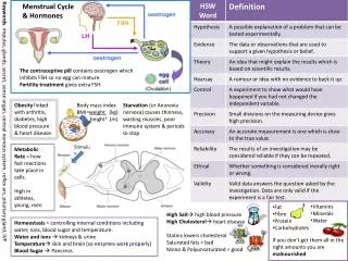
Requirements Overview • Highlights from the Stimulus Requirement Document (StRD) version 1.1 (12/11/07) • There shall be a source that produces light over the entire spectrum used by the instrument (0.4-2.2um) that can be located at the equivalent of the telescope image plane (Science source) • There shall be a source that produces light at 589nm +/-10nm that can be located at the equivalent of 90km focus (LGS source) P3K-IRD-0465 • There shall be a source that is bright enough to be visible to the eye at full beam size (4.5” diameter) that can be located at the equivalent of the telescope image plane (Alignment Mode) • At least one source shall have a pupil stop at the location of the telescope pupil image • The Science source shall be adjustable in focus by +/-25mm • The Science source shall have a translation range of +/- 10mm in the x and y directions • The LGS source should be adjustable in focus from the equivalent of 80 to 120km • Stimulus shall have a seeing-size effective spot size of 0.5-1” for NGS • All sources shall have variable intensity • The stimulus package shall be configured such that the LGS and Science sources can be used at the same time • The stimulus package shall fit within current box
Optical Design Top View White Light Aerotech Stages X, Y, Z 594 Laser Aerotech Z Stage 80:20 Beamsplitter OAP1 Beam Entrance Hole (old fold mirror) Pupil Mask Flipper FM2 FM1 OAP2 Conjugate Telescope Focus
The New P3K Stimulus • All reflective design; pupil shared by all 3 sources • We will re-use 3 pieces of the current stimulus • The white light source and fiber in the rack • The HeNe alignment laser • The fold mirror (and Newport motor) on the AO bench will be retained in its current location and height • All other pieces in the current stimulus package will be removed • We will build the new stimulus package on a duplicate breadboard (24” x 24”) at JPL • Work will be done by April 9, May 9 at latest
Rack Design Front View New additions are in RED Newport Versastar 0.5” filter wheel c = 460 nm c = 1550 nm
Light Source Issues • White Light Source magnitudes • R-band (WFS) = 2.3 • K-band (Pharo) = -0.3 • The new white light will be 30% fainter than the old white light due to beamsplitter and reflective surface loss • The 632 nm alignment laser will project in multi mode when using the white light fiber (2 lobes in V-band), although most of the light (>85%) remains in the core of the fiber output. • The 632 nm alignment laser may be used as a single mode alignment source through the 594 nm laser fiber with the 594 fiber output Aerotech stage set to 0 km. • The 2 laser source intensities may be reduced by using a combination of neutral density filters mounted in a manually selectable filter wheel placed at the output of both lasers.
594 and 632 Magnitudes For the 594 and 632 nm laser magnitudes of the new design, we calculated the overfill loss at the pupil in the stimulus, assumed 20% loss at the fiber couple, 2% loss at each optical surface, and an 80:20 beam splitter at the 594 nm input * The 594 nm laser stage must be moved to 0 km for 632 source alignment
Science Focal Spot Diagrams • 450 to 2200 nm Spot Diagram at center, +/- 1 mm, and +/- 10 mm
Alignment Tolerances • Stimulus source total wavefront error requirement = 300 nm / (2)1/2 = 212 nm • OAP vendor (B-Con) guarantees /4 with best effort to /8. /4 OAP fabrication surface error results in 112 nmwavefront error for 2 OAPs • Final wavefront error = [(alignment errors)2 + (fabrication errors)2]1/2 = 212 nm • Wavefront error from alignment will not exceed 180 nm to satisfy total wavefront error requirement
Cable / Controller Additions • The existing Aerotech EPAQ controller will be modified to run 7 stages (it currently controls 3 stages) • The 4 new Aerotech stages in the stimulus will connect to the existing Aerotech controller via 4 10 meter cables, which will be bundled together
Stimulus Cover Handles Pupil Access Output opening Side Pupil Access
Final Cost List Items in hand are green, items on order are blue
Pencil Beam • A pencil beam laser source, a fold mirror, and a magnetic kinematic mount will be permanently added outside of the stimulus cover for AO lab testing. These additions will not vignette any part of the stimulus beam nor will they block the off-axis relay mounts. The second fold mirror will be permanently fixed to the magnetic mount’s twin for quick and easy assembly. Permanent Mount Temporary Fold Permanent Fold Permanent Laser
Phase Screens • During the design review, CD jewel case covers were suggested as a simple cost-effective method to generate various spot size disks in the output beam of the stimulus. • Once the stimulus is working, we can try this • The 6” diameter door on the top of the cover should allow easy access and jewel case placement (pieces of plexi-glass?)