Download
1 / 23
230 likes | 499 Vues
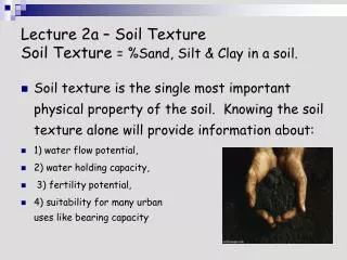
Tutorial 3: Slope stability and soil nailing walls. Deep Excavation LLC. DeepXcav 2010 – Advanced course. 1. INTRODUCTION .

E N D
Tutorial 3: Slope stability and soil nailing walls Deep Excavation LLC DeepXcav 2010 – Advanced course 1
INTRODUCTION DeepXcav is a software program for braced excavations in soils with 2D limit-equilibrium and non-linear analysis methods, and structural verification of all elements (with AISC, ASD, Eurocodes). It offers the ability to analyze walls with multiple braces (tiebacks) in multilayered soils. The non-linear analysis considers elastoplastic behavior for the whole soil-wall-support system. The program also offers the ability to perform traditional limit-equilibrium analyses. The graphical interface is completely interactive and the input is simplified to a great extend. The program utilizes archives of wall types, structural and soil materials, ground anchors etc. The analysis can be performed in either an utlimate state or at a service state (allowable design or LRFD). The program offers the ability to automatically set all critical settings according to the desired design methodology. The program also offers the ability to perform slope stability analyses with soil nails. Corso Paratie, Milano 30 settembre 2009 DeepXcav 2010 – Advanced course 2
Slope tab Import DXF Launches Options Soil nailing options Options for design approach (load combination) Select this check to perform slope stability analysis for current stage. Quick tool for analysis method (Bishop, Spencer, MP) Press to perform only slope calculations (after general analysis has been performed) Quick tool for type of failure surface, and radius search Draw tools for slope center, radius, etc. DeepXcav 2010 – Advanced course
Review of all slope options: 1. Method 1. Select this button 2. Select analysis method 3. Parameters for Morgenstern-Price method Max number of iterations Convergence tolerance (typical 0.1% or 0.01%) Preliminary slice width Minimum number of slices DeepXcav 2010 – Advanced course
Review of all slope options: 2. Center Center location can be a point or a rectangular grid. The coordinates can be exact or relative to the top left coordinates of the left wall. Option: “Use only one point for the analysis”, then one center point will be used. Rotation angle is used in Rectangular search option. DeepXcav 2010 – Advanced course
Review of all slope options: 3. Radius search Radius location can be a point or a rectangular grid. In the default option the radius search starts from the bottom of the left wall to the bottom of the model. Option: “Use single radius search”, to use one radius. Option: “Specify exact radii limits”, use a starting and an ending radius. Option: “Specify exact coordinates”, the radius will vary from a user specified starting point to a user specified ending point. DeepXcav 2010 – Advanced course
Review of all slope options: 4. Active/Passive Within this tab the user can specify an active angle and a passive angle limit. These angle limits can be searched within a range from the initial active or passive limit angle. Select the “Use block analysis” option to force the failure surface to be a block type. In this case, you will have to define a starting point and an ending point. DeepXcav 2010 – Advanced course
Review of all slope options: 5. Supports • Support resistance can be included within a slope stability analysis. Researchers are recommending that caution is exercised when support reactions are applied. In specific, with inclined ground anchors, vertical slope or wall movements can result in the relaxation of anchor force and thus the stabilizing support contribution can be reduced. • “Include support reactions”, will include the support reactions as calculated from the wall analysis. • “Include support service capacities”, will include the minimum design capacity of a support. This option is most consistent with all design approach methods such as EC7 etc. • “Include support ultimate capacities”, will include the minimum ultimate capacity of a support. • “Ignore support forces” will ignore all support reactions. DeepXcav 2010 – Advanced course
Review of all slope options: 6. Misc Wall shearing: When a failure surface intersects a wall, then the shear capacity of the wall can be included in the analysis. This shear capacity is always limited by the net soil resistance below the cut point (passive-active, but to a depth that is automatically limited to account for wall stiffness and displacement compatibility). When the project is designed with an allowable approach, then the ultimate wall capacity can be reasonably used. In this case, the wall shear capacity is multiplied by the appropriate factor to obtain the ultimate wall capacity. Soil-shear on Vertical faces of end and start slices: This option is used in Bishop analyses. Within this tab, if vertical faces are encountered in the start or end, the shear and horizontal loads on vertical faces can be calculated from at-rest or active earth pressures. The number of vertical intervals, controls the points where the pressures will be integrated to give the total force. Include tieback shear on slice base: In Bishop analysis: When a ground anchor fixed part intersects a slice then this option increases the normal reaction and available shear at the intersected slice.
Review of all slope options: 7. 3D Loads From this tab we can control how 3D loads are included in the slope stability analysis. The default option looks within the horizontal support spacing limits and includes the 3D loads only found within. Otherwise, 3D loads can be included within specified limits from a minimum to a maximum out-of-plane coordinate relative to the base wall. DeepXcav 2010 – Advanced course
Review of all slope options: 8. Tension crack From this tab we can control the tension crack simulation. Tension crack depths can be automatically calculated, if a layer has cohesion or undrained shear strength. Otherwise, the user can specify his own tension crack depth. The tension crack can be filled with water if the last check box is selected (recommended option). DeepXcav 2010 – Advanced course
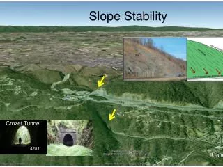
Slope stability example. • Typical example for generating a slope stability analysis • Select one point center and rectangular search • Define single radius and two radii limits.
Soil F Soil properties: F A. General Soil name: F (this appears in the boring) Description: Sand Detailed soil description. Soil type: Sand gt= 120 pcf : Total unit weight gdry= 120 pcf : Dry unit c‘ = 100 psf : Effective cohesion F’ = 32 degrees : Effective friction angle V = 0.35 Poisson’s ratio D. Bond Ultimate bond for soil nails= 50 psi Press OK
Project geometry Soil nails placed at 5 ft horizontal.
Edit the tieback sectionsRename tieback section 4-Strand to nail 1 and use #9 rebar in a 4inch hole.Select Grade 60 steel (if not available you will have to define from material properties)
Click on draw nail group to draw soil nailsThen draw from the top to the bottom on the vertical face
Select one point for the center of the slope stability circle. Click the mouse on the screen where desired (track the moving cross).
Select one circle radius. Move mouse near excavation bottom (failure surface redraws dynamically as the mouse moves). Select the excavation bottom as show below.