Download
1 / 21
210 likes | 375 Vues
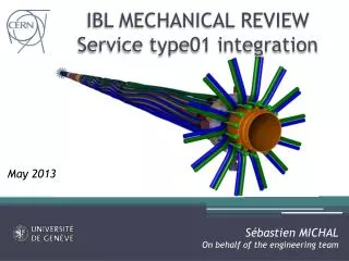
IBL BP Integration and Service Organisation. SUMMARY BP insertion BP services Type01 bundles Cooling lines I-flex. Beam Pipe Integration. MPC positioned and surveyed in front of the marble table in building 113 (ATUIBLS_0132) Beam Pipe guided on the marble table’s rail

E N D
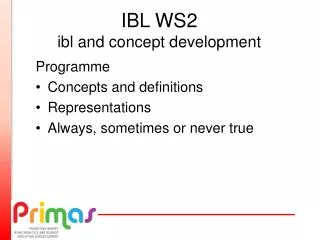
IBL BP Integration and Service Organisation • SUMMARY • BP insertion • BP services • Type01 bundles • Coolinglines • I-flex
Beam Pipe Integration • MPC positioned and surveyed in front of the marble table in building 113 (ATUIBLS_0132) • Beam Pipe guided on the marble table’s rail • ~0.2 mm clearance with respect to IPT MARBLE TABLE MPC with IPT
Beam Pipe Integration • Successfully inserted on the IPT on AUGUST 2013
Beam Pipe Services • 3 thermocouples and 12 heaters wires on each side • Integration very tricky because of a lack of space: • New flange with nitrogen connection • IBL service wrapping • Thermocouple connectors (removed)
IBL SERVICE OVERVIEW • Intermediate Flexes (28, identical) • Type01 bundles (28, 4 flavors, see ATU-SYS-CD-0007) • Cooling lines (14 inlet (OD 1.7 mm) and 14 outlet (OD 2.2 mm) IP Type01 bundles and cooling lines PP1 AREA I-Flexes
GLOBAL IBL INTEGRATION SEQUENCE • A stave is loaded on the IPT (see Franck’s talk) • Installation of the corresponding bundle on both sides • Installation of the corresponding I-flexes on both sides • Test • Next stave loading… Or • A stave is loaded on the IPT with flex saver • Test • Next stave loading + test… • Type01 bundle loading • I-flexes loading • Test
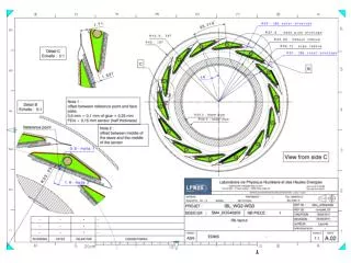
IBL TYPE01 BUNDLE • 5 Z stoppers are implemented all along the type01 bundle to manage the needed overlength (CTE mismatch) and strain relieve the PP0 area. • Manufacturing according to drawing ATUIBLP_0034. • Bundle n°06 reached most of the requirements • Last point to be solved: • End of the lacing at PP1 • Type of cable (gage24)
TYPE01 BUNDLE TOOLING • Z stopper tool (ATUIBLS_0131) for both bundle flavors (A and C): • Z stopper position within 0.1mm • No force in the bundle • Pre-shaping of the waves • A complete procedure has been developed and validated • A technician has been trained to perform this task
TYPE01 BUNDLE INTEGRATION In collaboration with SLAC team Type 1 bundles are systematically protected Type 1 bundles precisely mounted in Z stoppers HYSOL 9394 is applied (masking technic) Type 1 bundles are systematically checked (Geometry + electrically) Several type01 bundle integration tests done on the IPT
COOLING LINE INTEGRATION In collaboration with Eric Vigeolas CCPM • Requirements: • Cooling lines precisely cut • CTE mismatch management (1.6 mm contraction at -40°C) • Loading without interferences with respect to the neighboring type01 bundles CL compression by 2 mm overlength Single Z stopper CL location (both sides)
COOLING LINE INTEGRATION In collaboration with Eric Vigeolas CCPM • Compression tests on the CL: • CL integrated on the IPT with Z stoppers of bundles • Dynamometer is implemented on the EoS ring • 2 mm compression of the CL at PP1 • Maximum force before and after buckling are saved • Compression of the CL from 2mm to 0.5 mm (cooling configuration)
I-flex Integration Integration requirements: • I-Flexes nominal dimensions according to drawing ATUIBLP_0098 (C.BAULT) • No disconnection of connectors if a small offset in Z is present (+/-2mm). • Mounting / un-mounting without applying any force on the IPT. A tool is going to be used to systematically check the nominal length and the height of each I-flex
I-flex Integration In collaboration with Ole ROHNE’s team • Test set-up to evaluate the reaction forces corresponding to a +- 2 mm displacement with respect to nominal position. • Procedure: • I-Flex installed in nominal position • I-Flex is pulled +1 and +2 mm • Back in nominal • I-Flex is compressed -1 and -2 mm +2mm -2mm
I-flex Integration In collaboration with Ole ROHNE’s team
I-flex Integration on IPT • Both mounting and un-mounting tests have been done on the real IPT • I-flex integration is performed after having mounted the stave and type one bundles • No specific tools are needed to mount the I-flex on the IPT (no pressure on the IPT) • Nospecific tool is used to un-mount the I-flex, excepted a specific brucelle (no pressure on the IPT)
KEY POINTS OF INTEGRATION OF IBL SERVICES • The stave is integrated on the IPT • The CL Z stopper is already glued on the CL and positioned on the IPT • Type one bundles are integrated on the IPT • The cable board is not loaded in the IPT clips • I-flex integration • We connect the I-flex on the cable board starting with the innermost connector • We connect the I-flex on the stave flex connectors starting with the innermost connector • The stave flex is clipped on the IPT • The cable board is clipped on the IPT • The NTC sensor is bonded on the cooling sleeve • Is the space compatible with the bonding process?
INTEGRATION OF IBL SERVICES I-flex 1rst connected 1rst connected NTC sensors
CONCLUSION: • Type01 bundles: • Procedure has been developed and validated • Technician trained • I-Flex: • Geometry controls • Pull tests • CL Integration • 1st integration test • Z stopper prototyping • General • Envelope Jig to validate the envelope before the closing of the MPC
CONCLUSION: what remains to be done / solved / tested • Type01 bundles: • What is the delivery plan ? • Accelerate the Z stopper preparation process: 7 weeks (glue hardening, too long): • Other glue • Accelerated cure (check integration clearances) • I-Flex: • Production schedule ? • Safe mating after integration of the complete I-flex set • Cooling Integration • Validation test • Z stopper production (material, bonding process) • Tool to cut the cooling line precisely • Z stopper compatibility with cooling fitting tightening tool (LAPP/ Didier LAPORTE)
CONCLUSION: what remains to be done / solved / tested • General: • Integration test with final production material • Integration of the PP1 area (extremely tight packing and still missing sealing ring, cooling fittings…) • Detailed integration procedure of the services on the IPT • Feedback from LAPP about wrapping compatibility of the new BP diablo