Download
1 / 48
500 likes | 985 Vues
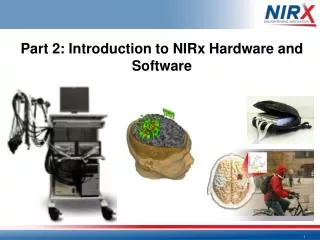
Part 2: Introduction to NIRx Hardware and Software. NIRS Software Basics. NIRx Software NIRStar Instrument-Control Software nirsLAB Topographic Analysis Software NAVI Tomographic Imaging Software. NIRStar realtime cortical activation viewing.

E N D
NIRx Software NIRStar Instrument-Control Software nirsLAB Topographic Analysis Software NAVI Tomographic Imaging Software
NIRStarrealtime cortical activation viewing. NIRStar Software – Instrument Control & Recording • Open license • BCI/Neurofeedback • Real-time cortical viewing • Real-time data streams • Real-time block averages • Hyperscanning • Optode position registration
The NIRStar Channel Setup gives users the chance to precisely define an illumination pattern: the time-multiplexing order which the sources illuminate in one full scan Sources used in measurement Steps used per full scan NIRStar Channel Setup Detectors used in measurement Illumination pattern of sources firing per scan Scans per sec. (sampling rate/ temporal resolution)
The topolayout gives a simple 2D representation of the montage layout, facilitating easy viewing of channel activity. Numbering is issued with sources listed first, then detectors (e.g., 1-2 is source #1 paired with detector #2, etc.) NIRStar Topo Layout
NIRStar Probe Setup Ultility The probe setup utility gives a 3D representation for the channel activation.
NIRx Product Overview Software – Topographic Analysis • nirsLAB • Open licensed • Sophisticated topographic data analysis • Detailed cortical views with activation maps • Flexible options for data manipulation (spike removal, filtering, etc.) • SPM1 and SPM2 (group-level) analysis
NIRx Product Overview SPM results shown right for right-leg balance. The results can be viewed in multiple images, with or without probe and standard EEG locations. Probes are shown in red (sources) and yellow (detectors). Right: 2D layout Software – nirsLAB - Topographic Analysis
NIRx Product Overview SPM results shown right for right-leg balance. 3D layout Software – nirsLAB - Topographic Analysis
NIRx Product Overview SPM results shown right for right-leg balance. High-resolution brain with glass head layout Software – nirsLAB - Topographic Analysis
NIRx Product Overview SPM results shown right for right-leg balance. MNI brain with glass head layout Software – nirsLAB - Topographic Analysis
NIRx Product Overview In addition to SPM1 and SPM2, nirsLAB allows block average viewing at any given relative time (to the event onset time = 0), including full animations. Software – nirsLAB - Topographic Analysis
NIRx Product Overview Software – Tomographic Analysis • NAVI • Open licensed • Sophisticated tomographic data analysis • Source analysis from from discrimination • Flexible options for data manipulation (spike removal, filtering, etc.) • Detailed cortical views with activation maps
NIRx Product Overview NAVI – Tomographic Analysis – fNIRS activation on MR scans
fNIRS – Hardware Overview Calibration Phantom for testing and setting proper gain settings for detectors (and sources, in some cases) Probes (optodes) for sending (sources) and receiving (detectors) light. Note: sources may be LED or Laser, depending on the system and application. detector (LED) source
fNIRS – Hardware Overview Headgear – Retains probes for steady and orthogonal placement against skin. Amplifier – this unit both powers the sources and detectors. It also digitizes the detector signal. Also, in some cases, sends and receives TTL trigger pulses
NIRx Development 2004 2000 2013 Mobile Studies Hyperscanning 2012
NIRx Hardware • Headgear = NIRScap • Systems = NIRS Imaging Systems • NIRSport • NIRScout and NIRScout Extended
NIRScap - Headgear Concept Optodes: - low profile - variety of solutions - organized cables Retaining layer: - outer cap compression - adjustable shape - whole head Conforming cap: - free configurations - multi-modal - Comfortable
Optodes LED Illuminator (2-Wavelength -> 760nm & 850nm Fiber optic Detectors Optode Placement
Fiber support arm The fiber support arm system is highly-flexible and relieves cable tension on optodes, increasing comfort and maintaining data quality.
Static test phantom All NIRx systems use the NIRx static phantom for automated procedures that ensure that the system and its components are working properly. The black case (shown above) provides a dark environment for testing detector and source performance.
Technical basis of instrumentation • CW measurement (DC Intensity changes) • Most economic, compact, robust technology • Adequate for hemodynamic activation measures • Scalable modularity – from 8-64 detector ch., & 8-128 source ch. • Simultaneous wavelength illumination • Frequency modulated – 760nm (1.0kHz) & 850nm (1.3KHz) -> Hb/HbO (more, other WL custom options) • Oxy and deoxy => strength over fMRI (only deoxy) • Source switching – Time- Multiplexing • Dynamic measuremement (no competing sources) • Scan rate typically 4-15Hz (62.5Hz max.)
Tandem mode • Two identical instruments (any model) • Channel number doubled • Integration in software, seamless operation as one instrument NIRSport Tandem Setup (pictured left) for 16-source and 16-detector measurements NIRScout Extended Tandem Setup (pictured right) for a maximum of 128-source and 64-detector measurements
NIRx Product Overview NIRSport 8-8 and NIRSport 16-16 Tandem Portable/Wearable System
NIRSport Mobile NIRS System • Ideal for: • Mobile or movement-based studies • Studies requiring extremely lightweight headgear • Child • ASD • 8 Active LED sources • 8 Active Detectors • 6-hour battery • Runs on power as well • Can be used in Tandem for 16/16 measurements
NIRScout High-Density NIRS System • - Up to 64 sources and 32 detectors • 8-bit trigger input and output • Options for Hybrid LED/Laser sources • Can have as few as 8 sources and 4 detectors • Can be used in tandem operation for doubling sources and detectors on a single subject
NIRScout High-Density NIRS System • Ideal for: • full-head monitoring • high-density/maximum spatial resolution recordings • Hyperscanning • Multi-modal studies • Animal studies
NIRScout Extended 8-bit Trigger OUTPUT EEG EMG Brain stimulation(TMS, etc.) Direct, programmable digital (TTL) control of other systems
NIRScout High-Density NIRS System • LED/Laser Hybrid System • Lasers capable of 4-wavelength measurements • Use of new port (shown here) allows choice of either LED or Laser sources
NIRScout High-Density NIRS System • LED/Laser Hybrid System • Lasers capable of 4-wavelength measurements • Standard set: • 685nm • 780nm • 808nm • 830nm
NIRS Instrumentation Highlights Comprehensive: - Wearable Large-scale/High-density - Wide range of accessories Scalable: - Upgradeable, Tandem Mode - Hyperscanning Integrated: - Experimental control (Trigger I/O) - Single cross-platform control software - Multi-modal ready (EEG, fMRI, TMS, …)
Thanks! ... Questions?