Download

1 / 32
320 likes | 495 Vues
A Meta-model for Inte gra ting Safety Concerns into System Engineering Processes. Wednesday 17 th April 2013. LURPA – ENS Cachan (France) Pierre-Yves Piriou Jean-Marc Faure MRI – EDF R&D Clamart (France ) Gilles Deleuze.

E N D
A Meta-model forIntegratingSafetyConcernsinto System Engineering Processes Wednesday 17th April 2013 LURPA – ENS Cachan (France) Pierre-Yves Piriou Jean-Marc Faure MRI – EDF R&D Clamart (France) Gilles Deleuze
Outline A Meta-model forIntegratingSafetyConcernsinto System Engineering Processes • Context and objective of the work • General industrial concern • Application domain: safety of nuclear power plants • Objective • Related work • Contribution • General description of the meta-model • Details • Illustration: instantiation of the meta-model • Brief description of the example • Some instance diagrams • Conclusion and outlook
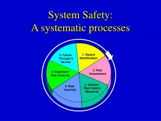
Context and objective of the work General concern • Bridging the gap between System Engineering and SafetyAnalysis. Meta-model Safety Analysis System Engineering
Context and objective of the work Safety of Nuclear Power Plant (1) • This field considers Phased Mission Systems. Each mission phase determines: • A specific system structure • A specific success criterion • Specific failure and recovery processes Power Phase 2: Production phase Phase 1: Power increasing Phase 3: Power decreasing t
Context and objective of the work Safety of Nuclear Power Plant (2) • Many components can be repaired. • The component states are defined by the combination of one failure mode and one operation mode Failure Mode: stochastic evolution Operation Mode: deterministic evolution OK RUN repair failure OVERSPEED OFF repair failure State OVERSPEED-LEAK State RUN-OK State RUN-OK State OVERSPEED-OK State OFF-OK State RUN-LEAK State OFF-RUPTURE RUPTURE LEAK
Context and objective of the work Safety of Nuclear Power Plant (3) • Redundancy policies declarations have to be formalized. • A component can spare another one simply by changing its operation mode OK OK REDUNDANCY P1 RUN RUN repair repair failure failure OVERSPEED OVERSPEED OFF OFF repair repair P2 failure failure RUPTURE RUPTURE LEAK LEAK
Context and objective of the work Objective • To refine an existing System Engineering meta-model for easily defining models dealing with safety concerns: • Phased Mission Systems (PMS) • Repairable components • Realistic failure/repair scenarios • Redundancy policies • Safety Analysis knowledge • System Engineering • Meta-Model • Resulting Meta-model • Requirements • Architecturing • … • Failure mode • Redundancy • …
Related work Integratingsafetyconcernsinto SE processes • For the first steps of the system lifecycle: • [Guillerm 2011]: Safetyrequirementselicitation. • [Cancila 2009]: Integrating the preliminaryriskanalysisprocess. • It isassumedthatthese issues are solved. • [David 2010]: A method for modelingrealisticfailure/repair scenarios in a complex system design. • Phased Mission Systems not considered • NorRedundancyPolicies
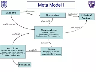
Related work The existing System Engineering meta-model • [Pfister2012]: A meta-model for formalizingsystemsknowledge, based on functional architecture patterns. • A meta-model is a model of model. • It shouldbeused in addition to the SE processes.
Outline A Meta-model forIntegratingSafetyConcernsinto System Engineering Processes • Context and objective of the work • General industrial concern • Application domain: safety of nuclear power plants • Objective • Related work • Contribution • General description of the meta-model • Details • Illustration: instantiation of the meta-model • Brief description of the example • Some instance diagrams • Conclusion and outlook
Contribution The Meta-model • Meta-model specified with an UML class diagram and OCL constraints • Minimal describing classes for modeling: • Mission phases • Component states: • Operation modes • Failure modes • Effect of a componenton a function • Redundancy policies
Contribution Details: Component State • A component maybe in several States. • A state isdefined by one Failure Mode and one Operation Mode • The possible evolutionbetweenthe states are drivenby probabilityrates Non-faulty State repairRate Faulty State failureRate
Contribution Details: Redundancy Policy (1) • During the phase P, the functionF must beperformed by a set of n components C = {ci}iϵ[1,n]. If itdoesn’t do, thereis a redundant component CR (CR C ).
Contribution Details: Redundancy Policy (2) • For validating the redundancypolicy, the current state of the component CR must be in the set of m statesS = {Si}iϵ[1,m].
Contribution Details: Redundancy Policy (3) • In order to spare the failed components, the component CRhas to bepowered on the state SR (SR S ). When a reconfiguration occurs, the allocation of components to functionsmaybechanged.
Outline A Meta-model forIntegratingSafetyConcernsinto System Engineering Processes • Context and objective of the work • General industrial concern • Application domain: safety of nuclear power plants • Objective • Related work • Contribution • General description of the meta-model • Details • Illustration: instantiation of the meta-model • Brief description of the example • Some instance diagrams • Conclusion and outlook
Illustration : Instantiation of the Meta-Model Example description (1) • Twofeeding turbo pumps Reference input Sensors PID Controller Water level control system FTP1 Steam Generator Other Components FTP2 Secondarycircuit of the power plant water steam
Illustration : Instantiation of the Meta-Model Example description (1) • Twofeeding turbo pumps • One Function: « To supplyenough water » • Threeconsidered mission phases • P1: To increase the power (0%Pn < Power < 60%Pn) • P2: To produceenergy (60%Pn < Power < 100%Pn) • P3: To decrease the power (0%Pn < Power < 60%Pn) Reference input Sensors PID Controller Water level control system FTP1 Steam Generator Other Components FTP2 Secondarycircuit of the power plant water steam
Illustration : Instantiation of the Meta-Model Example description (2) : FTP1 RUN; FTP2 RUN • P1: Only one pump is active. In case of failure of that pump, the spare component is activated. • P2: The two pumps are active. In case of failure of one of them, the other is over-speeded • P3: same as phase P1 : FTP1 OFF; FTP2: RUN : FTP1 OFF; FTP2 OVERSPEED : FTP1 RUN; FTP2 OFF Power/Pn Failure of FTP1 Repair of FTP1 100 % 60 % Failure of FTP1 Curve of power t 150 P1 P2 P3
Illustration : Instantiation of the Meta-Model Instance diagram for the Components (Modes) FTP1 FTP2
Illustration : Instantiation of the Meta-Model Instance diagram for the Components (Tables of attributes values) • Each combination of Operation Mode and Failure Mode is a state that is featured by failure (λ) / repair (μ) rates.
Illustration : Instantiation of the Meta-Model Instance diagram for a redundancypolicy • R2.1: If the set of components {FTP1} does not perform fittingly the function F during the phase P2, … spared aimedFunction definedFor
Illustration : Instantiation of the Meta-Model Instance diagram for aredundancypolicy • …and if the component FTP2is available (i.e. its current state is in the set of states {(RUN, Ok)}, … spared redundant aimedFunction available definedFor
Illustration : Instantiation of the Meta-Model Instance diagram for aredundancypolicy • …then FTP2has to be powered on the state (OVER-SPEED, OK)for participating in the achievement of F. spared redundant aimedFunction available definedFor rescue
Conclusion and Outlook Conclusion and Outlook • The meta-model offers a framework for integrating safety analysis into SE processes. • The meta-model has been implemented with the modeling tool arKItect® . • For assessing safety attributes, a dynamical model is necessary. • The definition of an algorithm for automating the construction of a formal dynamical model from an instance of this meta-model is an ongoing work.
Question Time Thank you for your attention A Meta-model forIntegratingSafetyConcernsinto System Engineering Processes Wednesday 17th April 2013 LURPA – ENS Cachan (France) Pierre-Yves Piriou Jean-Marc Faure MRI – EDF R&D Clamart (France) Gilles Deleuze
References (1) [1] F. Pfister, V. Chapurlat, M. Huchard, C. Nebut, and J.-L. Wippler, “A proposed meta-model for formalizing systems engineering knowledge, based on functional architectural patterns,” Systems Engineering, vol. 15, pp. 321–332, Autumn 2012. [2] R. Guillerm, N. Sadou, and H. Demmou, “Combining FMECA and Fault Trees for declining safety requirements of complex systems,” in ESREL 2011, C. . G. Soares, Ed., Troyes (France), september 2011, p.1287-1293. [3] D. Cancila, F. Terrier, F. Belmonte, H. Dubois, H. Espinoza, S. Gérard, and A. Cuccuru, “Sophia: a modeling language for model-based safety engineering,” in MoDELS ACES-MB, Denver, Colorado, USA, October, 6th 2009, pp. 11–25. [4] P. David, V. Idasiak, and F. Kratz, “Reliability study of complex physical systems using sysml,” International Journal in Reliability Engineeringand System Safety, vol. 95, no. 4, pp. 431 – 450, 2010. [5] OMG, Uml 2.0 OCL specification, Object Management Group, 2003. [6] A. Villemeur, Reliability, Availability, Maintainability and Safety Assessment, Methods and Techniques. Wiley, 1992.
References (2) [7] G.-R. Burdick, J.-B. Fussell, D.-M. Rasmuson, and J.-R. Wilson, “Phased mission analysis: A review of new developments and an application,” IEEE Transactions on Reliability, vol. R-26, pp. 43–49, April 1977. [8] L. Meshkat, L. Xing, S. Donohue, and O. S.K., “An overview of the phase-modular fault tree approach to phased mission system analysis,” in Proceedings of the International Conference on Space Mission Challenges for Information Technology, Pasadena, CA, USA, July 2003, p. 10. [9] M. Kothare, B. Mettler, M. Morari, P. Bendotti, and C.-M. Falinower, “Level control in the steam generator of a nuclear power plant,” in Decision and Control, 1996, Proceedings of the 35th IEEE (10 pages), vol. 4, Kobe, Hyogo, Japan, December 11th-13th 1996, pp. 4851–4856. [10] H. Zhang, B. de Saport, F. Dufoura, and G. Deleuze, “Dynamicreliability: Towards efficient simulation of the availability of a feedwater control system,” in NPIC-HMIT 2012, San Diego, USA, July 22-26 2012. [11] H. Aboutaleb, M. Bouali, M. Adedjouma, and E. Suomalainen, “An integrated approach to implement system engineering and safety engineering processes: Sasha project,” in ERTS2012 (6 pages), Toulouse, France, February 2nd 2012.
A software for multi-scale and multi-job design. • Developed by the French company: Knowledge Inside • The tooloffers a graphical and collaborative environement. • Twolayers of design: • The Domain SpecificLanguage design (meta-model) • The System design (instanciation)
PyCATSHOO (EDF R&D) • PythonicContext (Object-Oriented) for modeling and computing the HybridStochasticAutomaton • A computation engine for the Monte Carlo simulation • Using Knowledge Bases • [12] H. Chraibi, Dynamic reliability and assessment with PyCATSHOO: Application to a test case.in PSAM (10 pages), Tokyo, Japan, April, 14th-18th 2013.
Definition of a Mission Phase (step 1) • The Mission Phase determines for the system: • The system structure • The failure and recoveryprocesses • The successcriteria
Definition of the effect of a component on a function (step 3) • The components whichperform a function have to reach a quantified goal in order to fittinglyachieveit. • If a functionisallocated to a component, thenthat component performsthisfunctionwith an achievement rate to bedefined.