Download
1 / 14
140 likes | 473 Vues
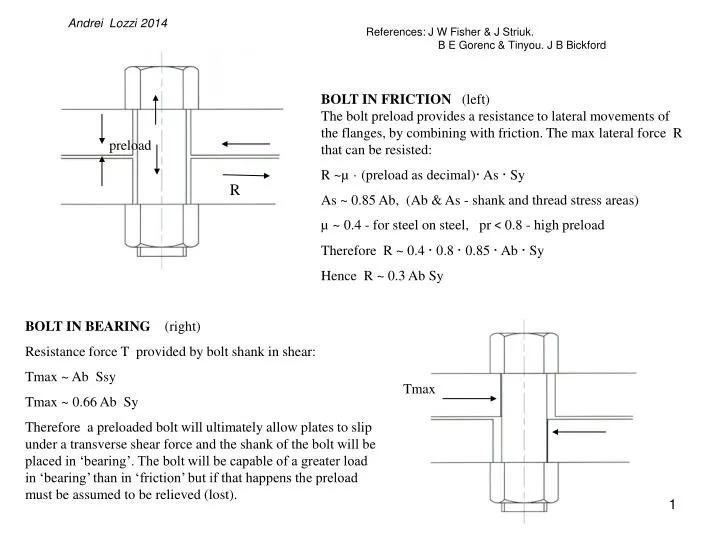
Andrei Lozzi 2014. References: J W Fisher & J Striuk. B E Gorenc & Tinyou. J B Bickford. BOLT IN FRICTION (left) The bolt preload provides a resistance to lateral movements of the flanges, by combining with friction. The max lateral force R that can be resisted:

E N D
Andrei Lozzi 2014 References: J W Fisher & J Striuk. B E Gorenc & Tinyou. J B Bickford BOLT IN FRICTION (left)The bolt preload provides a resistance to lateral movements of the flanges, by combining with friction. The max lateral force R that can be resisted: R ~µ · (preload as decimal)· As · Sy As ~ 0.85 Ab, (Ab & As - shank and thread stress areas) µ ~ 0.4 - for steel on steel, pr < 0.8 - high preload Therefore R ~ 0.4 · 0.8 · 0.85 · Ab · Sy Hence R ~ 0.3 Ab Sy preload R BOLT IN BEARING (right) Resistance force T provided by bolt shank in shear: Tmax ~ Ab Ssy Tmax ~ 0.66 Ab Sy Therefore a preloaded bolt will ultimately allow plates to slip under a transverse shear force and the shank of the bolt will be placed in ‘bearing’. The bolt will be capable of a greater load in ‘bearing’ than in ‘friction’ but if that happens the preload must be assumed to be relieved (lost). Tmax
We have 2 strips of material, each with 7 equally disposed holes of the same diameter. The lower strip is drawn with broken lines and its holes with slightly smaller diameter to make the two strips distinguishable.
How to determine the load of the most heavily loaded bolt, if a pattern of bolts are placed in shear. Assume we have two plates with matching linear pattern of holes. If then the plates are bolted together and plates are rotated with respect to each other by a small angle
when the 2 strips are superimposed. We note that the lateral displacement of the holes increases as we move away from the centre of the bolt patter (the centre hole). If these strips had been bolted together and one strip rotated as shown above w.r.t. the other the centre bolt would not be subjected to any shear elongation but as the distance from the centre increases the shear elongation and therefore the shear stress would increase proportionally. A large number of tests have shown that using normal tolerances (±5 to10% Db) and using medium strength material, the greater the distance from the centroid of the bolt pattern, the greater will be the likelihood of bolt shear failures.
D - Perpendicular distance from centre to the line of the force Centroid or centre of bolt pattern F - Force D The force F has to be resisted and a bolt pattern of 5 bolts is nominated to do the task. Here we set out the method of calculating the shear load in each bolt in the pattern. The bolts have to resist a moment equal to M=F x D (ie F cross product D)and the shear force F , acting on the pattern. The moment M is a vector that is vertical to this diagram.
F fs = F/n To simplify these drawings, only the effect on 3 bolts will be shown. Considering the shear force first: The shear force F is shared equally by all bolts, ie each take fs = F/5. Generally the force on bolt i due to shear force F Taken as vectors: fsi = F/n
D r F fs fmi Considering the moment next: The moment M=F x Dis typically distributed unevenly between the bolts. The further away a bolt is from the centre of rotation (ie the centroid) the greater will be its elongation under shear, hence the greater will be its share of the moment. The share of M taken by each bolt will be proportional to | r |. For the pattern chosen above we must note that all fmi for the four corner bolts are of the same magnitude but of different direction. The exception is the centre bolt for which fm = 0 fmi = c ri
D r F fmi The moment cont’d: Shear force due to moment proportional to ri The contribution from all bolts equal to the moment Since the moment is : we have: Therefore: We can now calculate the load at each bolt location, due to just the moment. fmi = c ri Σri fmi = F x D Σ c ri² = F x D M= F x D c = (F x D)/ Σri²
fs fmi The moment tries to rotate the plates while sliding w.r.t. each other. Hence the bolts holes further away from the centre will displace laterally more than the holes nearer to the centre. The furthest bolts are subjected to the greatest shear elongation, any bolt at the centre will just rotate and carry no shear load due to the moment.
ft3 ft2 ft1 Each bolt takes the vector sum of these 2 components shown above fti=fs+fmi. The resulting force on each bolt can have quite different magnitudes, eg ft1> ft3> ft2. Usually a bolt is chosen of a diameter and grade that can safely carry the largest shear load. That size and grade bolt is then used at all locations. Some bolts are as result underutilised but if the situation warrants and safety can be reasonably assured, two or more sizes of bolts may be used. Some bolt pattern are better than others at sharing the load more equally between the bolts.
If bolt preloaded to 80% of its yield strength in tension, is subjected to more than about 30% of its shear strength, The bolt will yield and the preload will be relieved.
Fisher & J Striuk found that structural plates bolted together, subjected to an out of plane moment, as shown at bottom left, the bolt pattern will approximately hinge 1/6th from the bottom of the flange. The rotation or hinging may occur as shown at the bottom left figure, if the components show little deformation (ie are stiff) with respect to the moment.
A bolt pattern as seen on wheel to hub connection. Usually both the hub and the wheel are stiff with respect to lateral forces, between the tyre and the road.
There is a multitude of possible failure modes at plates or sheets, riveted or bolted together, subjected to significant shear forces