4.3 Global Internet
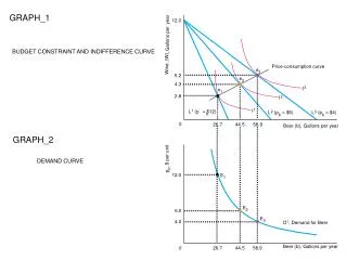
4.3 Global Internet. How to connect a heterogeneous collection of networks to create an internetwork ? How to use the simple hierarchy of the IP address to make routing in an internet somewhat scalable ?. NSFNET backbone. Stanford. ISU. BARRNET. MidNet. ■ ■ ■. regional. Westnet.

4.3 Global Internet
E N D
Presentation Transcript
4.3 Global Internet • How to connect a heterogeneous collection of networks to create an internetwork? • How to use the simple hierarchy of the IP address to make routing in an internet somewhat scalable?
NSFNET backbone Stanford ISU BARRNET MidNet ■ ■ ■ regional Westnet regional regional Berkeley PARC UNL KU UNM NCAR UA Internet Structure Recent past Internet in 1990
Internet in 1990 • end user sites • e.g., Stanford University • connect to "service provider" networks • not a single network, but consists of multiple physical networks connected by routers and bridges • service provider networks • e.g., BARRNET, a provider network that served sites in the San Francisco Bay area • built from a large number of point-to-point links (e.g., DS-3 or OC-3 links) that connect to routers
regional networks • many providers served a limited geographic region • nationwide backbone • connects regional networks • in 1990, this backbone was NSFNET, funded by National Science Foundation (NSF)
service provider • different providers may have different ideas about • the best routing protocol to use within their network • how metrics should be assigned to links in their network • each provider's network is usually a single autonomous system (AS) • AS: a network that is administered independently of other ASs
4.3.1 Subnetting • Subnetting deals with address space utilization • Original intent of IP addresses • the network part would uniquely identify exactly one physical network • Problem of address assignment inefficiency • class C with 2 hosts (2/255 = 0.78% efficiency) • class B with 256 hosts (256/65535 = 0.39% efficiency)
Subnet • add another level to address/routing hierarchy • reduce the total number of network numbers that are assigned • idea • take a single IP network number and allocate the IP addresses with that network number to several physical networks • a perfect use of subnetting is a large campus or corporation that has many physical networks
Subnet mask • define variable partition of host part • a single network number can be shared among multiple networks involves configuring all the nodes on each subnet with a subnet mask
subnet mask enables a subnet number • hosts may be on different physical networks but share a single network number • example, to share a single class B address among several physical networks, we could use a subnet mask of 255.255.255.0 (all 1s in the upper 24 bits and 0s in the lower 8 bits) • the top 24 bits are network number • the lower 8 bits are host number • the top 16 bits identify the network in a class B address
three parts address • network part (16 bits) • subnet part (8 bits) • host part (8 bits)
Subnet mask: 255.255.255.128 Subnet number: 128.96.34.0 128.96.34.15 128.96.34.1 R1 H1 Subnet mask: 255.255.255.128 128.96.34.130 Subnet number: 128.96.34.128 128.96.34.139 128.96.34.129 H3 R2 H2 128.96.33.1 128.96.33.14 Subnet mask: 255.255.255.0 Subnet number: 128.96.33.0 Subnet Example
Exactly one subnet mask per subnet • H1 • IP address: 128.96.34.15 • subnet mask: 255.255.255.128 • subnet number: 128.96.34.0 • Defines the subnet number of the host and of all other hosts on the same subnet • take bitwise AND of “IP address” and “subnet mask” • example, 128.96.34.15 AND 255.255.255.128 equals 128.96.34.0
When a host wants to send a packet to a certain IP address • perform a bitwise AND of its own subnet mask and the destination IP address • if the result equals the subnet number of the sending host • the destination host is on the same subnet and the packet can be delivered directly over the subnet
if the results are not equal • the packet needs to be sent to a router to be forwarded to another subnet • example, if H1 is sending to H2, then H1 ANDs its subnet mask (255.255.255.128) with the address for H2 (128.96.34.139) to obtain 128.96.34.128 • this does not match the subnet number for H1 (128.96.34.0), so H1 and H2 are on different subnets • H1 has to send packet to its default router R1 then to H2
Router with/without subnetting • simple IP • entries of forwarding tables is of the form (NetworkNum, NextHop) • support subnetting • entries of forwarding tables is of the form (SubnetNumber, SubnetMask, NextHop)
find the right entry in the table • the router ANDs the packet's destination address with the SubnetMask for each entry in turn • if the result matches the SubnetNumber of the entry, then this is the right entry to use • it forwards the packet to the next hop router indicated • router Rl of the “subnet example” (Figure 4.26) would have the following entries
continuing with the example, a datagram from H1 being sent to H2 • Rl would AND H2's address (128.96.34.139) with the subnet mask of the first entry (255.255.255.128) • compare the result (128.96.34.128) with the network number for that entry (128.96.34.0) • since this is not a match, it proceeds to the next entry • this time a match does occur, so Rl delivers the datagram to H2 using interface 1, which is the interface connected to the same network as H2
Datagram Forwarding Algorithm D = destination IP address for each entry (SubnetNum, SubnetMask, NextHop) D1 = SubnetMask & D if D1 = SubnetNum if NextHop is an interface deliver datagram directly to D else deliver datagram to NextHop
4.3.2 Classless Routing (CIDR) • Classless InterDomain Routing (CIDR, pronounced "cider") • CIDR addresses two scaling concerns in the Internet • the growth of backbone routing tables as more and more network numbers need to be stored • the potential for the 32-bit IP address space to be exhausted well before the 4 billionth (= 232) host is attached to the Internet • CIDR assigns block of contiguous network numbers to nearby networks
CIDR tries to balance the following • minimize the number of routes that a router needs to know • the need to hand out addresses efficiently • CIDR helps to aggregate routes • uses a single entry in a forwarding table to reach a lot of different networks by breaking the rigid boundaries between address classes
example, consider a hypothetical AS with 16 class C network numbers • instead of handing out 16 addresses at random, we can hand out a block of contiguous class C addresses • suppose we assign the class C network numbers from 192.4.16 through 192.4.31 • the top 20 bits of all the addresses in this range are the same (11000000 00000100 0001)
what we have effectively created is a 20-bit network number-something that is between a class B network number and a class C number
7 24 A: 0 Network Host 14 16 B: 1 0 Network Host 21 8 C: 1 1 0 Network Host IP addresses: (a) class A; (b) class B; (c) class C
CIDR allows the prefixes (network numbers) can be of any length • convention: place a /X after the prefix where X is the prefix length in bits • the example above, the 20-bit prefix for all the networks 192.4.16 through 192.4.31 is represented as 192.4.16/20 • if we want to represent a single class C network number, its prefix is 24 bits long, we would write it 192.4.16/24
Routing protocol can use CIDR to deal with "classless" addresses • it must understand that a network number may be of any length • network numbers are represented by (length, value) pairs • length: gives the number of bits in the network prefix, e.g., 20 in the above example
Internet Service Provider (ISP) network has to provide Internet connectivity to a large number of corporations and campuses (customers) • if we assign prefixes to the customers in such a way that many different customer networks connected to the provider network share a common, shorter address prefix, then we can get even greater aggregation of routes
example, assume that eight customers served by the provider network have each been assigned adjacent 24-bit network prefixes • those prefixes all start with the same 21 bits • all of the customer are reachable through the same provider network • it can advertise a single route to all of them by just advertising the common 21-bit prefix they share
128 135 Route aggregation with CIDR
IP Forwarding Revisited • CIDR means that prefixes may be of any length, from 2 to 32 bits • it is possible to have prefixes in the forwarding table that "overlap," in the sense that some addresses may matchmore than one prefix • example1 • we might find both 171.69 (a 16-bit prefix) and 171.69.10 (a 24-bit prefix) in the forwarding table of a single router • a packet destined to, say, 171.69.10.5, clearly matches both prefixes • 171.69.10 would be the longest match in this case
example2 • a packet destined to 171.69.20.5 would match 171.69 and not 171.69.10 • in the absence of any other matching entry in the routing table, 171.69 would be the longest match
4.3.3 Interdomain Routing • Internet is organized as autonomous systems • each of which is under the control of a single administrative entity • a corporation's complex internal network might be a single AS, as may the network of a single Internet service provider • the following figure shows a simple network with two autonomous systems
Basic idea behind autonomous systems • provide an additional way to hierarchically aggregate routing information in a large internet, thus improving scalability
Routing scopes • intradomain routing • routing within a single autonomous system • each AS can run whatever intradomain routing protocols it chooses • interdomain routing • routing between autonomous systems • different ASs share with each other the reachability information - descriptions of the set of IP addresses that can be reached via a given AS
Challenge of interdomain routing • the need for each AS to determine its own routing policies • example, a routing policy implemented at a particular AS might look like this • whenever possible, I prefer to send traffic via AS X than via AS Y, but I'll use AS Y if it is the only path, and I never want to carry traffic from AS X to AS Y or vice versa • such a policy would be typical when I have paid money to both AS X and AS Y to connect my AS to the rest of the Internet, and AS X is my preferred provider of connectivity with AS Y being the fallback
because I view both AS X and AS Y as providers, I don't expect to help them out by carrying traffic between them across my network (called transit traffic) • the more ASs I connect to, the more complex policies I might have • especially when you consider backbone providers, who may interconnect with dozens of other providers and hundreds of customers, and have different economic arrangements (which affect routing policies) with each one
Two major interdomain routing protocols • Exterior Gateway Protocol (EGP) • Border Gateway Protocol (BGP)
Exterior Gateway Protocol (EGP) • Overview • designed for tree-structured Internet • EGP did not allow for the topology to become more general • In this simple treelike structure, there is a single backbone, and autonomous systems are connected only as parents and children and not as peers • concerned with “reachability”, not optimal routes
Border Gateway Protocol (BGP) • The replacement for EGP • BGP is known for being rather complex • BGP-4 : the current version • BGP assumes that the Internet is an arbitrarily interconnected set of ASs (accommodate nontree-structured internetworks)
Large corporation “Consumer” ISP Peering point Backbone service provider Peering point “Consumer” ISP “Consumer” ISP Large corporation Small corporation Internet Structure Current Internet
Large corporation “Consumer” ISP Peering point Backbone service provider Peering point “Consumer” ISP “Consumer” ISP Large corporation Small corporation Internet Structure • Today’s Internet consists of an interconnection of multiple backbone networks (called service provider networks) and they are operated by private companies rather than the government • Sites are connected to each other in arbitrary ways • Some large corporations connect directly to one or more of the backbones, while others connect to smaller, nonbackbone service providers
Large corporation “Consumer” ISP Peering point Backbone service provider Peering point “Consumer” ISP “Consumer” ISP Large corporation Small corporation Internet Structure • Many service providers exist mainly to provide service to “consumers” and these providers must also connect to the backbone providers • Often many providers arrange to interconnect with each other at a single “peering point” • It is hard to discern much structure at all in today’s Internet
Given this rough sketch of the Internet, define • Local & transit traffic • local traffic: traffic that originates at or terminates on nodes within an AS • transit traffic: traffic that passes through an AS
Large corporation “Consumer” ISP Peering point Backbone service provider Peering point “Consumer” ISP “Consumer” ISP Large corporation Small corporation • Three types of ASs • Stub AS • an AS that has only a single connection to one other AS • such an AS will only carry local traffic • example, small corporation • Multihomed AS • an AS that has connections to more than one other AS but that refuses to carry transit traffic • example, large corporation at the top of Figure 4.29
Large corporation “Consumer” ISP Peering point Backbone service provider Peering point “Consumer” ISP “Consumer” ISP Large corporation Small corporation • Transit AS • an AS that has connections to more than one other AS and that is designed to carry bothtransit and local traffic • example, backbone providers
BGP configuration • BGP speaker • the administrator of each AS picks at least one node to be a "BGP speaker," a spokesperson for the entire AS • BGP speaker establishes BGP sessions to other BGP speakers in other ASs • sessions are used to exchange reachability information among ASs
border gateway • AS has one or more border gateways • border gateways are the IP routers through which packets enter and leave the AS (forwarding packets), e.g., routers R2 and R4 • BGP advertises complete paths as an enumerated list of ASs to reach a particular network
128.96 Customer P 192.4.153 (AS 4) Regional provider A (AS 2) Customer Q 192.4.32 (AS 5) 192.4.3 Backbone network (AS 1) Customer R 192.12.69 (AS 6) Regional provider B (AS 3) Customer S 192.4.54 (AS 7) 192.4.23 Example of a network running BGP