ASSEMBLING THE PCB
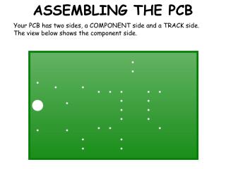
ASSEMBLING THE PCB. Your PCB has two sides, a COMPONENT side and a TRACK side. The view below shows the component side. ASSEMBLING THE PCB. First insert R1, the 330 ohm resistor. Note the colours, orange, orange, brown. ASSEMBLING THE PCB.

ASSEMBLING THE PCB
E N D
Presentation Transcript
ASSEMBLING THE PCB Your PCB has two sides, a COMPONENT side and a TRACK side. The view below shows the component side.
ASSEMBLING THE PCB First insert R1, the 330 ohm resistor.Note the colours, orange, orange, brown.
ASSEMBLING THE PCB The next two resistors, R2 and R3 are both 4.7 Kohms.Colours: Yellow, purple, red.
ASSEMBLING THE PCB Now insert the Zener diode. It is very important that it is inserted the correct way round. The band at the end is facing to the left.
ASSEMBLING THE PCB Next insert the IC holder. It has a notch at the top denoting which end is the top.
ASSEMBLING THE PCB There are two capacitors. They are both the same value, 2.2uF.They also must be inserted the correct way round. The stripe denotes the negative leg. negative leg.
ASSEMBLING THE PCB Finally for the component side, insert the buzzer. The positive connection is the longer leg and is at the top.
ASSEMBLING THE PCB Now turn the PCB over to look at the COPPER TRACK side.
ADDING THE LED Add the LED. This can be any colour you choose. The longer leg is the positive connection and faces upwards next to the “+” sign.Don’t push the LED in too far, leave about 5-10mm gap from the PCB.