Download
1 / 58
580 likes | 583 Vues
ACS850-04 New Industrial Drive Module. Petri Torniainen 12.5.2009. ACS850-04. Table of Contents. What is ACS850-04 HW features SW features Control connections Options PC Tools Documents Sales arguments. ACS850-04. ABB Industrial Drive.

E N D
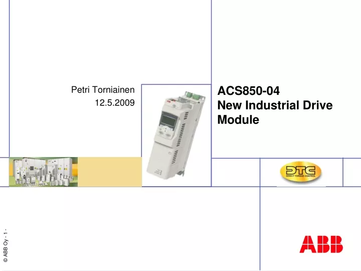
ACS850-04New Industrial Drive Module Petri Torniainen 12.5.2009
ACS850-04 Table of Contents • What is ACS850-04 • HW features • SW features • Control connections • Options • PC Tools • Documents • Sales arguments
ACS850-04 ABB Industrial Drive • Very flexible drives that are easy to be configured to meet the needs of various industries and applications • ABB Industrial drives are designed especially for applications in process industries such as: • Pulp & paper • Metals • Mining • Cement • Chemical • Oil & gas • Examples of applications: • Cranes • Winders • Extruders • Mixers • Wire drawing machines • Separators • …
ACS850-04 Drive modules • ACS850-04 is a drive module designed to be built into a customer’s own cabinet
Global LV Drive Market 70% of total drives market is under 75 kW Market Shares by Power Range (MUSD, Y2006)
ACS850-04 Market strategy - targets • Growth • In the new industries and applications • Low power market • In the module market • Strengthen position in the existing markets
ACS850-04 ACS850-04, Highlights • Easy and cost efficient cabinet assembly • Flexible hardware and software • Advanced diagnostics and maintenance assistant • Intuitive to use • Built-in Safe Torque Off (STO) • Memory unit for easy drive management • Improved DTC, high performance motor control • Advanced energy saving features
ACS850-04 Technology • Frames A and B: 1,1 – 7,5 kW • Frames C and D: 11 – 45 kW • DC-choke integrated as standard • Optional built-in EMC filter • Frames E0, E and G: up to 500 kW • New control unit JCON-11 (comes during Q2/2009) • In the beginning the control unit is JCON-01 • IO-options: F-series modules • Control and application technology: new fw that is partly based on the existing platforms • Control panel: ACS-CP-U +
Hardware 500 1,1 kW 500 380 V Basic technical data • Power range: 1,1 – 500kW • 1.1 - 400 kW at 400V • Voltage range: 380 – 500V • 380 – 480 V in the beginning • 500 V: target for release Q2/2009 IP20; frames A-E IP00; frame G
Hardware Hardware in brief • Optimized product for cabinet assembly • Side-by-side mounting • Compact, narrow design • Power terminals on top (up to 45 kW) enabling compact and EMC compliant installation • Plug-in terminals • I/O terminals • Power terminals up to 11 kW • 2 option slots for I/O extensions and encoders and 1 dedicated slot for fieldbus
Hardware Hardware in brief • Cover for the control unit • Consists of two parts • If TTL encoder or resolver modules are used, the lower part of the cover to be left out (no space for the connector) • The control panel holder is available as an option • Can be attached either to the control unit cover or cabinet door • Coated boards as standard • Fan supervision (≤ 45 kW) • Supervises, if the fan is rotating or not
Hardware Ambient conditions • Temperature: • - 10°C - 55°C • G frame up to 50°C • Derating above 40°C • Relative humidity: • Max. 95%, no condensation allowed • Altitude: • up to 4000 m • At 500V up to 2000 m • 1%/100 m derating above 1000m • Vibration: • Class 3M4 acc. to EN60721-3-3 • Climatic / environmental conditions: • Class 3K3, 3C2 acc. to EN60721-3-3
Hardware Ratings • Similar kind of ratings as in ACS800, but new names: ACS850-04ACS800 I2N continuous nominal rating without overload Icontmax ILd light duty IN (110% OL for 1 min.) IHd heavy duty Ihd (150% OL for 1 min.) IMax maximum allowed current Imax Note: IMax is always available for 10 sec at start and after that depending on the drive temperature • Reasons for the new naming policy: • Uniform naming policy throughout the LV AC Drives • More logical than the naming policy today • More in line with competitor offering (e.g. Siemens)
Hardware Ratings (frames A-D) Motor powers at 400 V supply voltage
Hardware Ratings (frames E0-G) 1 Overloadability at 40°C 40% 2 Overloadability at 40°C 30% Motor powers at 400 V supply voltage
Hardware Derating • Voltage derating: no derating needed from 400 V to 500 V • Temperature derating: 1%/1°C • Altitude derating: 1%/100m
Hardware Dimensions and mounting * standard, no options
Hardware Cable lengths • Max cable lengths: • Max. length of the STO cable is 25 m • Longer cable can be made by using extra relays • Max. length of the D2D link is 50 m
Software LOC MAIN MENU 2 PARAMETERS ASSISTANTS CHANGED PAR EXIT 16:31 ENTER LOC ASSISTANTS 2 Start-up Assistant Motor Set-up Application Speed control EXT1 Speed control EXT2 EXIT 16:31 SEL Software • Easy start-up • Macros: preprogrammed parameter settings • Start-up Assistant • Easy use • Intuitive parameter structure • Short/long parameter menus • I/O “mapping” • List of changed parameters • Flexibility • Extensive parameter settings • Limited block programmability as standard
Software LOC HELP Check: Excessive motor load, insuff. accel time, faulty motor, motor cables or connections. EXIT 16:31 OK LOC OVERCURRENT 01 FREQ AT FLT 10.8 Hz SPEED AT FLT 326 rpm TORQUE AT FLT EXIT 16:31 DIAG Software • Other added value features • Maintenance assistant • Reminds the user of the need of maintenance • Diagnostic assistant • Helps in locating the cause of the disturbance • Helps in restoring the problem • Advanced energy saving features • Energy efficiency optimizer • kWh/€/CO2 counter • Saved energy counter • Covering protections • Advanced thermal protection of IGBTs • Extensive preset and programmable protections
Software 500 0 Hz Improved DTC • DTC with enhanced features • No. 1 motor control on the market • Standard sw supports Asynchronous motors and Permanent magnet motors • Output frequency up to 500 Hz • Improved stand still ID run vs. ACS800
Control connections Standard control connections (JCON-01) 1 2 3 4 5 6 7 8 9
Control connections New control board • Some features needed for Industrial drive market are missing in JCON-01 new control board (JCON-11) • Sets the standard for the I/O and terminal numbering for the next generation Industrial drive products • Target for sales release: Q2/2009
Control connections JCON-11 changes vs. JCON-01 • Changes: • 2 more RO • 1 dedicated DIL added • 1 AO changed from V to mA • 1 DIO is left out • Dedicated PTC/KTY input left out • however, one of the DIs can be configured as a PTC input • No. of GND terminals is reduced, but terminal size increased • 7 segment display is left out • Modbus / D2D link: • galvanic isolation • can configured either as a D2D or Modbus link • FPGA and RAM changed • “Future proof” terminal numbering (may not be the same as in the picture) • Possibility to split DI’s as two groups (in JCON-01 DI + DI/O signals were isolated as one group, in JCON-11 they are isolated as two groups that can be split) • New MU with bigger memory • New and old ones are not compatible with each other
Control connections Standard control connections (JCON-11) • Connections: • 3 RO • 6 DI (one can be used as a PTC input) • 1 dedicated DIL • 2 DIO (can be used also as pulse input or output) • 2 AO (mA) • 2 AI (configurable mA or V) • Galvanically isolated RS485 link – can be configured alternatively either as Modbus or as D2D link • STO • Possibility for external 24 V DC supply • PC tool & control panel connection (can be used also for Modbus monitoring) • New Memory Unit • “Future proof” terminal numbering (may not be the same as in the picture)
Control connections Control connections - highlights • Safe Torque Off (STO) as standard • SIL3 (IEC 61508) / Safety category 4 (EN954-1) • Solutions for other safety features available by external options • Safe Stop 1 (SS1), SIL3 • Safe Brake Control (SBC), SIL2 • Safe Limited Speed (SLS), SIL2 • Safe Direction (SDI), SIL2 • Safe Speed Monitor (SSM) , SIL2 • Safe Stillstand, SIL2
Control connections ACS850-04 ACS850-04 Safe Torque Off interface STO
Control connections Control connections - highlights • High flexibility • Configurable DIO, can be used also as a pulse input or output • Drive to drive link as standard • Enhanced features like multicasting and supervision of follower status • Memory Unit • Stores the complete software and parameter settings • Makes the recommissioning of the unit fast and easy • Gives a possibility for software and parameter configuration at e.g. ABB or OEM workshop before sending it to customer • Possibility to connect 24VDC external power supply
Options Control & communication options 1/2 Two slots for control options 1 2 * When this module is used, the lower part of the control unit cover cannot be used
Options Control & communication options 2/2 One slot for communication options 3
Options Main circuit options • Flexibility with different main circuit options • Mains choke • EMC filter C3 • EMC filter C2 • Braking chopper (standard in frames A – D) • Braking resistor • Common mode filters • dU/dt filter • DC connection
Options EMC filter options Built-in option External option - Not available * Max. cable length 100 m
Options C3 (2nd env) EMC filters • Frames A – B • An external plug-in filter in the input terminals • Extra height ca. 150 mm • but due to the free space requirement above (200mm) the effect to the total height is much smaller! • If the height is critical, but there is space on the side, the external C2 filter is the solution • Frames C – G • Optional built-in EMC filter • In frames C and D possible to retrofit afterwards (a separate “lid” in the cover)
Options C2 (1st env) EMC filters • Frames A – D • An external filter (same filters as in ACSM1) • Frames E0 & E • Optional built-in EMC filter • Frame G • Not available
Options Dynamic braking options Braking choppers • In a common DC system several choppers can operate simultaneously Braking resistors • Available for different kind of pulse duty performance • Equipped with a thermal sensor as standard
Options Main circuit options
Options User interface – control panel Standard delivery • No control panel
Options User interface – control panel Assistant control panel • Option + J400 • With real time clock • Incl. Control panel holder in the unit • The same holder can be used also in the cabinet door
Options User interface – control panel Control panel holder in the unit • Option +J414 • Incl. control panel holder • No control panel – just a dummy panel with status LEDs
Options User interface – control panel Control panel holder in the door • Option + J410 • Incl. Control panel • Incl. Control panel holder • Incl. IP54 kit • Incl. 3m cable • No control panel holder in the unit
Options User interface – control panel Without control unit cover • Option + 0C103 • No control panel • No control panel holder
Options Control panel and control unit options
PC tools DriveStudio Commissioning, tuning and monitoring tool • Parameters setting and signal monitoring • Data logger and on-line signal monitoring • Backup and restore • Context sensitive helps • Start-up and Diagnostic Assistants
PC tools Sizing tool DriveSize • PC tool for sizing the motor and drive