Download
1 / 28
280 likes | 523 Vues
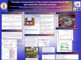
Measuring the PNC Spin-Rotation of Polarized Neutrons Traversing Liquid Helium. C.Bass, D.Luo, H.Nann, M.Sarsour, W.Snow Indiana University P.Huffman NIST C.Gould, D.Haase, D.Markoff North Carolina State University E.Adelberger, B.Heckel, H.Swanson University of Washington.

E N D
Measuring the PNC Spin-Rotation of Polarized Neutrons Traversing Liquid Helium C.Bass, D.Luo, H.Nann, M.Sarsour, W.Snow Indiana University P.Huffman NIST C.Gould, D.Haase, D.Markoff North Carolina State University E.Adelberger, B.Heckel, H.Swanson University of Washington
Seminar Overview • Weak NN-Interaction and the Meson-Exchange Model • Spin-Rotation Observable • Experimental Apparatus • Project Status
Nuclear Force:The Meson Exchange Model N N exchange mesons STRONG STRONG N N • separation distance < 0.8 fm: • repulsive core best described by spin-spin interaction between constituent quarks • separation distance > 2 fm: • one-meson exchange model yields excellent fit to data • intermediate separation distances: • various parameters need to be fitted by hand to both types of models
Weak NN Interaction N N exchange mesons WEAK (PNC) STRONG (PC) N N • Z, W are massive (effective range 10-3 fm) • the low energy weak interaction is essentially point-like • NN-interaction is strongly repulsive at short distances: • essentially no direct weak interaction at low energies • weak PNC potential characterized by weak meson exchange coupling constants • essentially all of the weak interaction physics is contained within the values of these coupling constants
q q W,Z q q N N p N N How Big is the Effect?
Which Mesons? • At low energies, light mesons should dominate the PNC potential because of their longer ranges • possible scalar and pseudoscalar exchanges are limited by Barton’s theorem: • CP invariance forbids coupling between J=0 neutral mesons and on-shell nucleons • p6, r0, r6, and v0 exchanges dominate the low energy PNC potential • the weak meson exchange coupling constants: fp , hr0, hr1, hr2, hr19, hv0, hv1
theoretical calculations of these coupling constants limited by uncertainties with quark model 6 independent coupling constants require 6 independent experiments the number of parameters can be reduced to 2 combinations of the couplings that dominate the observables: fp , and (hr0 + 0.6hv0). experimental uncertainties are somewhat increased by allowing for variations of the four minor degrees of freedom: hr1, hr2, hv1and residual inhv0 Meson Exchange Coupling Constants
polarized photons propagating through a “handed” medium undergo spin-rotation: cold neutrons propagating through spin-0 nuclei experience a similar rotation of the spin-polarization vector, but the “handedness” is the weak interaction Optical Spin-Rotation
Experiment Concept wPC + wPNC s . B s s s . pn pn l • cold neutrons are transversely polarized • neutrons travel through a helium target • PNC spin-rotation • PC spin-rotation • background B-field in target region • need to maximize PNC signal and minimize PC signal • Baxial = 0.5 Gauss [wMAG ~ 10 rad/m, • magnetic shielding [ Baxial < 100 mGauss • neutrons enter the analyzer • transmitted neutron flux contains information about the PC and PNC spin-rotation • goal of experiment: 6 2 3 10-7 rad/m sensitivity
neutron beam polarizer (SM) guide tube input coil outer mu-metal shield front target Experiment Overview LHe cryostat pi-coil rear target inner mu-metal shield output coil analyzer (SM) neutron flux detector
Neutron Beam • NG-6 beamline at NIST (Gaithersburg, MD) • energies in the 10-3 eV range (l ~ 5A) • beryllium filters provide high-energy cut-off • essentially 0% transmission below 3.4A • approx. 4% between 3.4A and 3.9A • about 90% above 3.9A
28 cm Neutron Beam Plate Curvature Radius ~ 10m Magnet Box Supermirror Polarizer and Analyzer • neutrons are polarized through spin-dependent scattering from magnetized mirrors • one spin-state is preferentially reflected by the mirror surface while the other state is transmitted and absorbed • designed to pass neutrons with the “up” spin state in the vertical direction • typical polarization: 98%
mu-metal sheets for field shaping main core return core beam to LHe target current sheet inner shield outer shield Input Coil • spins precess about aligned vertical fields as the neutrons pass adiabatically through the input coil • neutrons reach a current sheet at the back of the coil and pass non-adiabatically into the field-free region
Magnetic Shielding • mu-metal shielding surrounds the target region (including cryostat) • solenoidal coils inside shielding further reduces any residual axial B-fields
p-coil y beam direction z • a rectangular coil that produces a vertical magnetic field in the path of the beam • wound to prevent field leakage beyond the coil • designed so that the spin of a typical cold neutron will precess a total of p radians over the path of the coil p-coil x y y jp- f f x x
Helium Target and Operation cold neutron beam cold neutron beam TOP VIEW
Output Coil • neutron spins pass non-adiabatically through front of output coil • transverse component of spin adiabatically rotated into a horizontal B-field (y-axis) • the orientation of this (y-axis) B-field is flipped at a rate of ~ 1 Hz • spins then adiabatically rotated into the vertical (x-axis) direction of the analyzer • neutrons spins are now either parallel or antiparallel to the analyzer (depending on the target state and the orientation of the y-axis B-field)
3He Neutron Detector • neutrons detected through the following reaction: n 13He g3H 11H • charged reaction-products ionize the gas mixture • high voltage and grounded charge-collecting plates produce a current proportional to the neutron flux
Previous Version of Experiment (1996) • reached a sensitivity of ~2.6x10⁻⁶ rad/day of accumulated data • limited by statistics • systematic limits of the apparatus not reached wPNC(n,a) 5 (8.0 6 14[stat] 6 2.2[syst]) 3 10-7 rad/m
Redesign of Experiment • increase available statistics by improving reliability and decreasing downtime • increase the detected beam flux (NIST reactor upgrade: factor ~1.5) • use of superfluid helium • additional layer of mu-metal shielding • want a factor of x10 higher sensitivity in order to obtain a non-zero / null result: ~ 0.6310-6 rad / day of accumulated data estimate ~30 days of data for desired sensitivity
New Target • use of superfluid helium (~1.7K) • lower temp requires additional refrigeration: 1K-Pot • superfluid leaktight • non-magnetic and non-superconducting materials • stainless steel won’t work • new electrical feedthroughs (epoxy resin based) • liquid helium valve back target pi-coil front target electrical feedthroughs LHe valve 1K-pot (evaporation refrigerator) (surrounding canister not shown for clarity)
More Shielding • installation of 3rd layer of magnetic shielding: Cryoperm-10 • preliminary B-field mapping inside all three nested shields: • measured ~50mGauss in target region without solenoidal coils • previous version designed for 100mGauss background • want to further reduce this by 1/2 with trim coils
Current Status • field mapping of in/output coils and magnetic shielding • analysis of systematic effects • computer simulations • new target ready for machining • machining of target components • run at NIST in fall 2003