Advanced Polarized Positron Source Design for Future Linear Colliders
460 likes | 610 Vues
This workshop presentation explores the baseline undulator scheme for polarized positron production in the International Linear Collider (ILC). The complexity of the positron source is highlighted, including its various components, each deserving focused discussion. A detailed examination of the helical undulator, its magnetic field generation, and the interaction with laser photons is presented. Theoretical models for positron polarization and methods to create circularly polarized photons are discussed. This analysis aims to enhance production efficiency and precision in luminosity measurements for advanced accelerator physics.

Advanced Polarized Positron Source Design for Future Linear Colliders
E N D
Presentation Transcript
Ultimate polarization for ilc Alexander Mikhailichenko Cornell University, LEPP, Ithaca, NY 14853 Workshop on High Precision Measurements of Luminosity at Future Linear Colliders and Polarization of Lepton Beams October 3-5, 2010 Tel-Aviv University, Tel-Aviv, Israel
POSITRON SOURCE FOR ILC The undulator scheme of positron production has been chosen as a baseline for ILC Main advantage of this scheme is that it allows POLARIZED positron production In principle, positrons could be generated by positrons, so the linacs become independent Positron source is a complex system which includes a lot of different components and each of these components could be a subject of a separate talk
MORE DETAILED VIEW 200 m Helical undulator is a device for generation magnetic field of a type Radius of particle’s helix Wires Iron yoke Vacuum tube inside z Direction of currents λu=1 cm
Fragment from publication of Balakin-Mikhailichenko, Budker INP 79-85, Sept. 13, 1979. Scattering on the Laser radiation is the same process as the scattering on the electromagnetic wave. One comment about helical crystals first .
Helical (chiral) crystals Crystal structure MnSi and FeGe P.Bak, M.H.Jensen, J.Phys.C: Solid St.Physics, 13,(1980) L881-5 Helical structure demonstrates CsCuCl3,, FeGe, MgSi, Ba2CuGe2O7, MnS2
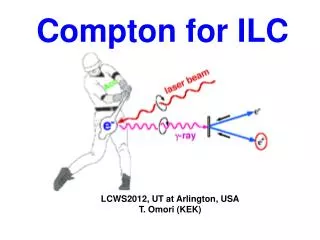
Laser bunch as an undulator The number of the quantas radiated by an electron by scattering on photons (real from the laser or virtual from the undulator) can be described as the following Formation length in undulator L- length of undulator – Length of interaction Written in this form it is clear that the photon back scattering (especially with 90o crossing angle) is a full equivalent of radiation in an undulator (as soon as the photon energy is much less, than the energy of particle). That is why undulator installed at >100 GeV line, where Eγ>10 MeV
(POLARIZED) POSITRONPRODUCTION Only gamma quanta can create positron (with electron) H.Olsen, L.Maximon, 1959 Longitudinal polarization as function of particle’s fractional energy E+/(Eγ-2mc2) +cross diagram Photon polarization Polarization is a result of selection positrons by theirs energy The ways to create circularly polarized photons in practical amounts V.Balakin, A. Mikhailichenko, 1979 E.Bessonov, A.Mikhailichenko1996 E.Bessonov 1992 1996 Polarized electron
Analytical calculations are possible Spectral density of radiation where is the energy of photon radiated straightforward The number of positrons generated by a single photon in the target becomes For E0=150 GeV, L=150 m, K2=0.1, τ=0.5 (rad units) Analytical formula taking into account finite length of undulator and finite diameter of target Zf,I - are the coordinates of undulator end and beginning calculated from the target position; E.Bessonov, A.Mikhailichenko, 1992 is a fraction of what is the target radius in respect to the size of the gamma spot at the target distance For = ½ , L=200m , λu=1cmδ=0.5, K=0.35, η=0.3 3
Spectral distribution and polarization schematics All higher harmonics have zero intensity in straight forward direction Angle to observer (radiation) and the energy of the photon are not independent Polarization curve needs to be convolved with the photon density This curve applied to each harmonics Hatched areas correspond to a passage of radiation through the collimator Diaphragm helps to enhance integrated photon polarization as each harmonics carries the photon polarization as a factor
KONN –interactive code for positron production with undulator
! POLARIZATION CURVE APPROXIMATION ! EP4=EP-0.4 EP6=EP-0.6 PP=0.305+2.15*EP4 IF(EP.LT.0.4)PP=PP-0.05*EP4-2.5*EP4**3 IF(EP.GT.0.6)PP=PP-0.55*EP6-2.65*EP6**2+0.7*EP6**3 ! PP=PP-0.55*EP6-2.6*EP6**2 IF(PP.GT.1.)PP=1. ! EP=POSITRON ENERGY/ Egamma-2mc2 Sentinel Depolarization occurs due to spin flip in act of radiation of quanta having energy where E1 stands for initial energy of positron. Depolarization after one single act Where stands for bremstrahlung cross section without spin flip, –the cross section with spin flip and is total cross section. Energy after radiation Rad. length 11 Depolarization ~5%
Example Code has ~3000 rows; Possibility for the file exchange with graphical and statistical Codes (JMP); Possibility for the file exchange with PARMELA; Period K-factor Few seconds for any new variant Efficiency and polarization
Before representing results of calculation let us demonstrate how different elements of conversion system look like
UNDULATOR(Cornell design) Complete design done; Diameter of cryostat -100mm System for magnetic measurement designed; Undulator includes correctors and BPMs; Current input one/few modules (ten) 3m possible Will be extended to 2 m long ~4m total
LITHIUM LENS If steady current I runs through the round conductor having radius a, its azimuthal magnetic field inside the rod could be describedas where magnetic field is measured in Gs, a –in cm, I –in Amperes. Current density comes to The particle, passed through the rod, will get the transverse kick This picture drawn for the focusing of electron beam to the target So the focal distance could be defined as the following
Li lens resume Utilization of Lithium lens allows Tungsten survival under condition required by ILC with Ne~2x10¹⁰ with moderate K~0.3-0.4 and do not require big-size spinning rim (or disc). Thin W target allows better functioning of collection optics (less depth of focusing). Lithium lens (and x-lens) is well developed technique. Usage of Li lens allows drastic increase in accumulation rate, low K-factor. Field is strictly limited by the surface of the lens from the target side. Liquid targets such as Pb/Bi or Hg allow further increase of positron yield. Plan is to repeat optimization for cone-shape Lithium rod.
Collimator for gammas Pyrolytic Graphite (PG) is used here. The purpose of it is to increase the beam diameter, before entering to the W part. Vacuum outgassing is negligible for this material. Heat conductivity ~300 W/m-oK is comparable with meals. Beryllium is also possible here, depending on task. Transverse dimensions defined by Moliere radius Positron component of cascade Gamma-beam. sg= 0.5cm, diameter of the hole (blue strip at the bottom) d=2 mm. Energy of gamma-beam coming from the left is 20 MeV.
PERTURBATION OF POLARIZATION Perturbation due to multiple scattering - absent Spin flip in a target ~5% Spin flip in an undulator - hardly mentionable effect Depolarization at IP ~5% Cinematic depolarization in undulator -absent CONCLUSIONSABOUT POLARIZATION Perturbation of spin is within 10% total (from creation). This number could be reduced by increasing the length of undulator, making target thinner (two targets) and beams more flat at IP.
SCHEME FOR PARTICLES SELECTION BY ENERGY Fast kickers required only for independent positron wing operation Achromatic bend with aperture diaphragm. T–is a target, L–is a short focusing lens, C–stands for collimator. F and D stand for focusing and defocusing lenses respectively. A stands for RF accelerator structure. A.Mikhailichenko, ” Independent Operation of Electron/Positron Wings of ILC”, EPAC 2006.MOPLS106.
ONE EXAMPLE Average polarization Filter on: 68.15% Filter off: 62.78% Efficiency Filter on: 1.49 Filter off: 1.796
Resulting efficiency and polarization calculated with KONN *readius of target is an equivalent of the radius of collimator
One another way to increase the polarization associated with installation of a second target. This is possible as the gamma beam loses its intensity after the first target ~13% only Collection of positrons in the longitudinal phase space is possible with combining scheme
Combining scheme doubles the positron yield and cuts in half the length of undulator increase of polarization Combining in longitudinal phase space could be arranged easily in the same RF separatrix in damping ring. Additional feed back system will be required for fast dump of coherent motion. COMBINING SCHEME Energy provided by acceleration structures A1 and A2 are slightly different, A1>A2. This combining can help in reduction of power deposition in target if each target made thinner, than optimal.
One another way to reconsider maximal polarization and luminosity achievable at IP It is associated with the spin-spin interaction of particles in the same bunch while the bunch is moving towards IP
Minimal emittance Fundamental restriction to the minimal emittance achievable in the electron/positron beam is A.A. Mikhailichenko, On the physical limitations to the Lowest Emittance (Toward Colliding Electron-Positron Crystalline Beams), 7th–Advanced Accelerator Concepts Workshop, 12-18 October 1996, Lake Tahoe, CA, AIP 398 Proceedings, p.294. See also CLNS 96/1436, Cornell, 1996, and in To the Quantum Limitations in Beam Physics, CLNS 99/1608, PAC99, New York, March 29- April 2 1999, Proceedings, p.2814. This formula can be obtained from counting the number of states in the phase space of a Fermi gas : The problem is that in the fully degenerated state polarization of beam is zero 28
SUPERCONDENSATION of ELECTRON GAS Magnetic dipole defines magnetic field around as In case a) and c) there is attraction by magnetic force. In case b) and d) there is additional repulsion Spin=1 Spin=0 Balancing attraction by magnetic force and repulsion by the same sign of charge, one can obtain Energy required bringing two electrons to the distance of Compton wavelength is i.e. pretty small compared with energy of transverse motion at IP especially 29
SUPERCONDENSATION AT IP – A WAY TO SUPER LUMINOSITY While beam in running to IP its density increases Spin=0 or spin=1 Is possible Fermi energy The condition for degeneration Fermi gas becomes more degenerative while its density increased. These conditions realizing better and better while beam traveling to IP. Taking into account interaction through magnetic momentum, it will possible to condense beam below Fermi-limit (couple of fermions behaves as a boson). 30
What is the limit for the number of electrons in a cluster Spin 0,1/2 The topic of super-condensation requires theoretical investigations
First suggested in 1992 E-166 experiment at SLAC Experimental test of polarized positron production With gammas generated by high energy beam in undulator Beam chamber 0.8 mm in dia Stretched wire to check the straightness Goes to 2.54 mm period for 50 GeV beam
Degree of longitudinal polarization for positrons and electrons as measured by the E166 experiment (preliminary). Results published in PRL, NIM
Maximal polarization can be achieved not only by collimation of gammas, but with selection of positrons by enrgy after the target. Separation of secondary particles (positrons or electrons) by energy is a key procedure in polarization gain. Generation of polarized electrons is possible in this method as well State with minimal emittance has zero overall polarization Mode detailed calculation required for process of squeezing the polarized beam to IP while spin-spin interaction taken into account CONCLUSIONS E-166 diffused any doubts about undulator-based positron production for ILC
Modeling of E-166 experiment with KONN Phase space right after the target Dependence of polarization seen in experiment
ILC Beam parameters important for conversion system gex=8 10-6 m rad -high edge gey=810-8 m rad –high edge bx ~200 m in undulator 50 sigma ~7 mm ; At the beginning of operation one can expect emittance degradation At Cornell the undulators having aperture Ø=8 mm tested so far; 6.35 (¼ in) designed. Daresbury deals with aperture Ø=5.23mm
3D scope of E-166 Undulator Soft bend Positron table Gamma-table
Doublet of Lithium lenses in Novosibirsk BINP Photo- courtesy of Yu Shatunov First lens is used for focusing of primary 250 MeV electron beam onto the W target, Second lens installed after the target and collects positrons at ~150MeV Number of primary electrons per pulse ~2·10+11; ~0.7Hz operation (defined by the beam cooling in Damping Ring) Lenses shown served ~30 Years without serious problem (!) 41
POLARIZED POSITRON PRODUCTION WITH STACKING IN DR If stacking in DR is allowed, then there is one additional way to generate polarized positrons. Calculations show that efficiency ~1.5% is possible for the first process with polarization ~75% Efficiencies of these processes are ~the same Polarized electron Realization of this method No lasers ! However, the Undulator-based scheme remains more advantageous
Depolarization arises as the spin changes its direction in coherent magnetic field of incoming beam. Again, here the deviation does not depend on energy, however it depends on location of particle in the bunch: central particles are not perturbed at all. Absolute value of angular rotation has opposite sign for particles symmetrically located around collision axes. This topic was investigated immediately after the scheme for polarized positron production was invented. This effect is not associated with polarized positron production exclusively because this effect tolerates the polarization of electrons at IP as well. Later many authors also considered this topic in detail. General conclusion here is that depolarization remains at the level ~5% Depolarization at IP E.A. Kushnirenko, A. A. Likhoded, M.V. Shevlyagin, “Depolarization Effects for Collisions of Polarized beams”, IHEP 93-131, SW 9430, Protvino 1993.
Spin flip in undulator Positron or electron may flip its spin direction while radiating in magnetic field. Probability: Probability of radiation: The ratio (K~1) Effect of spin flip still small (i.e. radiation is dominating).
KINEMATIC PERTURBATION OF POLARIZATION See A.Mikhailichenko, CBN 06-1, Cornell LEPP, 2006. Fragment from CBN 06-1